background image

12

pl

NA3  X X X X X X X X XX X

Wykonanie miernika: 

z bargrafem i wyświetlaczem cyfrowym

F

Kolor bargrafu:

trójkolorowy (R, G, R+G)

T

siedmiokolorowy (R, G, B, R+G, R+B, G+B, R+G+B)

M

Kolor wyświetlacza:

czerwony

R

zielony

G

Sygnał wejściowy:

wejście uniwersalne

U

Wyjście analogowe:

brak

0

uniwersalne prądowe 0/4...20 mA

1

uniwersalne napięciowe 0...10 V

2

Dodatkowe wyjście:

brak

0

wyjście cyfrowe RS-485 + 1 przekaźnikowe

1

wyjście cyfrowe RS-485 + 1 wyjście typu OC

2

2 przekaźnik

3

2 wyjścia typu OC

4

Napięcie zasilania:

95...253 V a.c./d.c.

1

20...40 V a.c./d.c.

2

na zamówienie*

X

Rodzaje zacisków:

gniazdo wtyk-śrubowe

0

Wykonanie:

standardowe

00

specjalne*

Próby odbiorcze:

bez dodatkowych wymagań

0

z dodatkowym atestem kontroli jakości

1

wg uzgodnień z odbiorcą

X

5.  KOD WYKONAÑ

Tablica 1

*  - tylko po uzgodnieniu z producentem

Содержание NA3

Страница 1: ...L TO ANALOGUE METER WITH A MULTICOLOUR BARGRAPH WITH SERIAL INTERFACE RS 485 NA3 INSTRUKCJA OBSŁUGI SZYBKI START Pełna wersja instrukcji dostępna na Full version of user s manual available at www lumel com pl USER S MANUAL QUICK START PL EN Zeskanuj mnie Zeskanuj kod Scan the code ...

Страница 2: ...y wzi æ pod uwagê wszystkie dostêpne wymogi ochrony przed w czeniem zasilania nale y sprawdziæ poprawnoœæ pod czeñ elektrycznych nie pod czaæ miernika do sieci poprzez autotransformator przed zdjêciem obudowy miernika nale y wy czyæ jego zasilanie zdjêcie obudowy miernika w trakcie trwania umowy gwarancyjnej powoduje jej uniewa nienie 2 MONTAŻ W tablicy przygotowaæ otwór o wymiarach 22 2 0 5 x 92 ...

Страница 3: ...erzonej na wyœwietlaczu i na bargrafie Na bargrafie zaznaczone s równie progi alarmowe w zale noœci od nastaw parametrów alarmowych i bargrafu Miernik automatycznie wygasza nieznacz ce zera NA3 0 10 20 30 40 50 60 70 80 90 100 Rys 3 Opis p yty czo owej mierników NA3 Funkcje przycisków przycisk akceptacji wejœcie w tryb programowania przytrzymanie przez oko o trzy se kundy wejœcie do wybranego pozi...

Страница 4: ...e do menu podgl du Po menu podgl du nale y poruszaæ siê za pomoc przycisku W menu tym dostêpne s tylko do odczytu wszystkie programowalne para metry miernika za wyj tkiem parametrów serwisowych Wyjœcie z menu podgl du odbywa siê za pomoc przycisku W menu podgl du jest równie mo liwe przegl danie zarejestro wanych wartoœci resl Wciœniêcie przycisku na parametrze resl powoduje wejœcie do menu przegl...

Страница 5: ...ie napisu Matryca programowania 3 sek 3 sek poprawne niepoprawne poruszanie siê po matrycy poruszanie siê po podgl dzie wejœcie do wybranego poziomu wyjœcie z matrycy 3 sek Wyœwietlanie wartoœci minimalnej Wyœwietlanie wartoœci maksymalnej wejœcie do zmian parametru Rys 4 Algorytm obs ugi miernika NA3 ...

Страница 6: ...prawnego kodu powoduje wejœcie do trybu programowa nia Rysunek 5 przedstawia matrycê przejœæ w trybie programowania Przyciskiem porusza siê po grupach parametrów g ównych np Chn bAr AL1 AL2 itd Wciœniêcie przycisku na danym poziomie powoduje wejœcie do parametrów tego poziomu Poruszanie siê po da nym poziome odbywa siê za pomoc przycisku W celu zmiany wartoœci nale y u yæ przycisku Aby zrezygnowaæ...

Страница 7: ... Górny próg Typ alarmu OpóŸn alarmu Podtrz alarmu Kolor dolny Kolor górny Dolny próg Górny próg Typ alarmu OpóŸn alarmu Podtrz alarmu Kolor dolny Kolor górny Ch ka ind wyj Param ch ki ind Prêdkoœæ tran Rodzaj tran Adres urz dz Wpis pa ram stan Zmiana has a Test wyœ i barg Zmiana czasu Kas wartoœci min Kas wartoœci max Rejestra cja Start rej Data rej Interwa rej Dolny próg Górny próg Typ alarmu Opó...

Страница 8: ...Zmiana migaj cej pozycji Zmiana migaj cej pozycji Zmiana migaj cej pozycji Wygaszanie nieznacz cych zer Zmiana migaj cej pozycji 0 9 1 Przyk ad zmiany wartoœci wybranego parametru ze zmian punktu dziesiêtnego parametr liczbowy Dopasowanie punktu dziesiêtnego Zmiana migaj cej pozycji Zmiana migaj cej pozycji Zmiana migaj cego przecinka Zmiana migaj cej pozycji Zmiana migaj cej pozycji 0 9 1 Rys 7 ...

Страница 9: ...r napiêcia 0 3 V X Pomiar napiêcia 0 10 V X Pomiar pr du 0 5 mA X Pomiar pr du 0 20 mA X Pomiar napiêcia 0 200 V X Pomiar napiêcia 0 600 V X Pomiar pr du 0 2 A X Pomiar pr du 0 5 A X NA3 XXXU Rezystancja wejœciowa dla wejœæ napiêciowych 4 M dla wejœæ 5 mA i 20 mA 4 dla wejœæ 2 A i 5 A 10 m 10 Natężenie prądu płynącego przez rezystor termometryczny 170 A Rezystancja przewodów łączących rezystor ter...

Страница 10: ...zakres do czanych napiêæ 5 24 V d c cyfrowe interfejs RS 485 protokó transmisji MODBUS ASCII 8N1 7E1 7O1 RTU 8N2 8E1 8O1 8N1 prêdkoœæ transmisji 2400 4800 9600 bodów maksymalny czas odpowiedzi na ramkê zapytania 300 ms Parametry pamiêci pamiêæ miernika rejestracji 750 próbek min interwa rejestracji 1 sec B d podstawowy 0 2 1 cyfra B êdy dodatkowe w znamionowych warunkach u ytkowania przy pomiarze ...

Страница 11: ...bargrafu programowalna Dok adnoœci bargrafu 0 5 segmentu Obs uga trzy przyciski Zapewniony stopieñ ochrony przez obudowê IP 40 od strony zacisków IP 20 Wymiary 96 24 125 mm wraz z zaciskami Masa 0 3 kg Moc pobierana 8 VA Odpornoœæ na zaniki zasilania wg PN EN 61000 6 2 2002 Kompatybilnoœæ elektromagnetyczna odpornoœæ na zak ócenia elektromagnetyczne wg PN EN 61000 6 2 2002 emisja zak óceñ elektrom...

Страница 12: ... 20 mA 1 uniwersalne napięciowe 0 10 V 2 Dodatkowe wyjście brak 0 wyjście cyfrowe RS 485 1 przekaźnikowe 1 wyjście cyfrowe RS 485 1 wyjście typu OC 2 2 przekaźnik 3 2 wyjścia typu OC 4 Napięcie zasilania 95 253 V a c d c 1 20 40 V a c d c 2 na zamówienie X Rodzaje zacisków gniazdo wtyk śrubowe 0 Wykonanie standardowe 00 specjalne Próby odbiorcze bez dodatkowych wymagań 0 z dodatkowym atestem kontr...

Страница 13: ...C Termoelement J Fe CuNi 30 1100 C K NiCr NiAl 50 1370 C N NiCrSi NiSi 100 1300 C E NiCr CuNi 20 850 C R PtRh13 Pt 0 1760 C S PtRh10 Pt 0 1760 C T Cu CuNi 50 400 C Rezystancja 0 400 0 4000 Napiêcie z bocznika 0 60 mV Napiêcie 0 3 V 0 10 V 0 200 V 0 600 V Pr d 0 5 mA 0 20 mA 0 2 A 0 5 A Wejœcie uniwersalne ...

Страница 14: ...e carried out by qualified skilled personnel and national regulations for the prevention of accidents must be observed l Beforeswitchingthemeteron onemustcheckthecorrectnessofconnections l Do not connect the meter to the network through an autotransformer l Before removing the meter housing one must switch the supply off and disconnect measuring circuits l Non authorized removal of the housing ina...

Страница 15: ...am e g are displayed After ca 3 seconds the meter is transiting automatically into the working mode in which it carries out the measurement and the display of the measured value on the display and the bargraph Depending on alarm and bargraph parameter settings alarm thresholds are also displayed on the bargraph The meter blanks automatically insignificant zeros Fig 4 Description of the NA3 frontal...

Страница 16: ... the safety code The pressure and hold down the key during 3 se conds causes the entry into the preview menu One must move on the preview menu by means of the key In this menu only all programmed parameters except servicing parameters are accessible to readout The exit from the preview menu is operated by means of the key In the preview menu it is also possible to review recorded resl values The p...

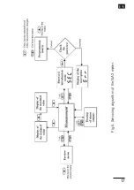
Страница 17: ...EN 17 Fig 5 Servicing algorithm of the NA3 meter ...

Страница 18: ... seC inscription alternately with the set value 0 by the manu facturer The introduction of the correct code causes the entry into the programming mode The fig 6 represents the transition matrix into the programming mode One can move on groups of main parameters eg Chn bAr1 Al1 Al2 etc by means of the key The pressure of the key on the given level causes the entry into parameters of this level The ...

Страница 19: ...larm support Lower colour Upper colour Output indiv charac Param of indiv charac Baud rate Kind of transm Device adress Inscrip of state param Password change Test of display bargr Time change Erasing of min value Erasing of max value Recording Start of recording Record date Record interval Lower threshold Upper threshold Alarm type Alarm delay Alarm support Lower colour Upper colour Param of indi...

Страница 20: ...EN 20 Fig 7 ...

Страница 21: ... V X Voltage measurement 0 10 V X Current measurement 0 5 mA X Current measurement 0 20 mA X Voltage measurement 0 200 V X Voltage measurement 0 600 V X Current measurement 0 2 A X Current measurement 0 5 A X NA3 XXXU Input resistance for voltage inputs 4 M for inputs 5 mA and 20 mA 4 for inputs 2 A and 5 A 10 m 10 Intensity of current flowing through the resistance thermometer 170 A Resistance of...

Страница 22: ...collector OC type voltageless OC type with npn transistor max load 25 mA range of added voltage 5 24 V d c Digital output interface RS 485 transmission protocol MODBUS ASCII 8N1 7E1 7O1 RTU 8N2 8E1 8O1 8N1 baud rate 2400 4800 9600 baud maximal response time to the request frame 300 ms Memory parameters meter memory record 750 samples min record interval 1 sec Basic error 0 2 1 digit Additional err...

Страница 23: ...m 45 segments in three colour execution 25 segments in seven colour execution Bargraph resolution programmable Bargraph accuracy 0 5 segment Servicing three keys Ensured protection degree EN 60529 through the casing IP 40 from terminal side IP 20 Dimensions 96 x 24 x 125 mm with terminals Weight 0 3 kg Power consumption 8 VA Resistance against supply decay acc EN 61000 6 2 2002 Electromagnetic com...

Страница 24: ...current programmed 0 4 20 mA 1 voltage programmed 0 10 V 2 Additional outputs Without output 0 RS 485 digital output 1 relay 1 RS 485 digital output 1 OC output 2 2 relays 3 2 OC outputs 4 Supply 95 253 V a c d c 1 20 40 V a c d c 2 on order X Kind of terminals socket screw plug 0 Execution standard 00 custom made XX Acceptance tests without an extra quality inspection certificate 0 with an extra ...

Страница 25: ...0 C N NiCrSi NiSi 100 1300 C E NiCr CuNi 20 850 C R PtRh13 Pt 0 1760 C S PtRh10 Pt 0 1760 C T Cu CuNi 50 400 C Resistance 0 400 Resistance 0 4000 Voltage from shunt 0 60 mV Voltage 0 3 V Voltage 0 10 V Voltage 0 200 V Voltage 0 600 V current 0 5 mA current 0 20 mA current 0 2 A current 0 5 A Universal input Input signals Table 2 ...

Страница 26: ...pis listwy zaciskowej 6 1 2 5 3 4 12 7 8 11 9 10 15 14 13 rezystor termometryczny termoelementy GND 5A 2A 20mA 5mA 600V 200V 10V 3V wyjœcie analogowe GND A B zasilanie RS 485 lub Alarm3 Alarm1 lub Alarm1 i Alarm2 a Description of the terminal strip lub or ...

Страница 27: ...jprzewodowym termoelement lub napiêcie 0 60 mV wejœcie napiêciowe wejœcie pr dowe 5 mA i 20 mA wejœcie pr dowe 2 A i 5 A b Connection way of input signals Resistance thermometer in two wire system Resistance thermometer in three wire system Thermocouple or 0 60 mV voltage 2 A and 5 A current input voltage input 5 mA and 20 mA current input ...

Страница 28: ...ik RS 485 1 wyjœcie typu OC otwarty kolektor 2 przekaŸniki 2 wyjœcia typu OC wyjœcie analogowe pr dowe lub napiêciowe c Connection way of digital and analogue output signals depending on the execution code RS 485 1 relay RS 485 1 OC type output open collector 2 relays 2 OC type outputs Current or voltage analogue output ...

Страница 29: ...rnika NA3 1 2 5 3 4 zasilanie Miernik NA3 1 2 5 3 4 zasilanie Miernik NA3 A GND B B A Komputer PC PD51 3 10 9 2 1 GND GND A B RxD TxD DB9 2 5 Komputer PC z kart RS 485 DB9 6 1 9 5 3 d Sposób po czenia interfejsu RS 485 NA3 meter NA3 meter PC ...

Страница 30: ...zenie kabla za pomoc bezpiecznika instalacji elektrycznej Wymagania wzglêdem kabla sieciowego reguluje norma PN EN 61010 1 punkt 6 10 Taking into consideration electromagnetic interference it is recommen ded to use shielded conductors for the connection of input and output signals The power supply must be connected by means of a two wire conductor with a suitable cross section ensuring its protect...

Страница 31: ...PL EN 31 ...

Страница 32: ...ka 1 65 022 Zielona Góra Poland tel 48 68 45 75 100 fax 48 68 45 75 508 www lumel com pl Pracownia systemów automatyki tel 68 45 75 228 45 75 117 Wzorcowanie tel 68 45 75 161 e mail laboratorium lumel com pl Export department tel 48 68 45 75 139 45 75 233 45 75 321 45 75 386 45 75 353 fax 48 68 32 54 091 e mail export lumel com pl Calibration Attestation tel 68 45 75 161 e mail laboratorium lumel ...

Отзывы: