background image

8

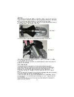
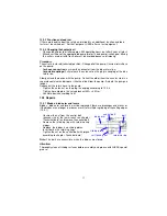
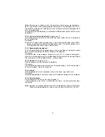
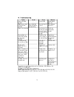
cutting

open

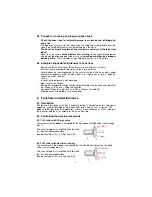
5.5 Periods for checking and replacing hose lines

-

Check the hose lines for external damage, tears, bends and inflating after
every use

.

-

The  operator  must  ensure  that  hose  lines  are  replaced  at  reasonable  intervals,
even if no safety deficiencies can be detected on the hose.

-

The hose line must be replaced 10 years after manufacture at the latest (see
label)!

-

Hose  lines  must  be 

checked  before  first  start-up

  of  the  technical  equipment

and then

 at least once a year to 

ensure a safe 

working condition by a properly

trained person

.  For examples of possible deficiencies, see 5.6 below.

5.6 Examples of possible deficiencies to hose lines

-

Damage to the external layer to the insert (e.g. chafing, cuts or tears).

-

External layer becoming brittle (tears to the hose material).

-

Deformations  not  corresponding  to  the  natural  shape  of  the  hose  when  under
pressure  or  depressurised,  or  when  bent,  e.g.  separation  of  layers,  bubbles,
squashed  areas,  bends.

-

Leaks.

-

Installation  requirements  not  observed.

-

Hose  leaves  the  fittings.

-

Damage or deformation to the fittings which alleviates the function and stability of
the fittings or the hose – fittings connection.

-

Corroded  fittings  or  metal  inserts,  which  alleviates  the  stability.

-

Storage times and period of use exceeded.

6

Functions and performance

6.1 Description

The device is designed such that a hydraulic piston is connected across two equal,
opposing,  symmetrical  blades  via  mechanical  joints  and  so  cuts  materials.  The
blades are designed for the application in terms of their geometry so that sliding of
the  material  being  cut  is  avoided  as  much  as  possible.

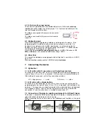
6.2 Controlling the working movements

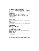
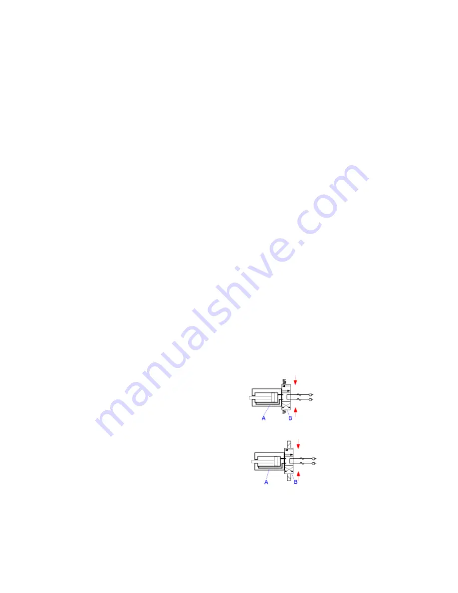
6.2.1 LSI cutter with 4/3-way valve

The movement of the blades is controlled by the star grip on the fitted valve (see first page
pos. 1).

The  circuit  diagram  is  simplified  here  to  make
the  function  comprehensible
(hydraulic cylinder (A) + 4/3-way valve (B).

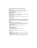
6.2.2 LSI cutter with electrical controls

The movement of the blades is controlled by the electric control unit on the fitted
valve (see first page pos. 2).

The  circuit  diagram  is  simplified  here  to  make
the  function  comprehensible
(hydraulic cylinder (A) + 4/3-way valve (B).

cutting

open

Содержание LSI 501

Страница 1: ...ottom 4 Cutter blades 5 Central bolt with self locking nut and lubricating nipple 6 Hydraulic cylinder 7 Hand guard 8 Hose line red pressure with quick connect socket 9 Hose line blue return with quic...

Страница 2: ...s 4 4 Maintenance and servicing instructions 5 5 Safety instructions for hose lines 6 6 Functions and performance 8 7 Connecting the device 9 8 Operation 11 9 Cutting 13 10 Dismantling of the device s...

Страница 3: ...suitable for underwater use up to 40 m 1 6 Devices with cylinder bottom are intended for externally controlled processes They are mainly used on robots cranes or other manipulators 1 7 The manufacture...

Страница 4: ...s Immediately report changes detected including changes to its operation to the appropriate office If necessary immediately shut off and secure the device Check all hydraulic and electrical lines hose...

Страница 5: ...detergents Use a fibre free cloth and ensure thorough cleanliness especially when rebuilding 4 3 When dismantling the device ensure that all escaping hydraulic fluid is collected that it does not ent...

Страница 6: ...t with the following fluids the hoses must immediately be cleaned acids soaps solutions diluted alcohol and fuels battery acids and ATF phosphate esters It is also essential that the hose lines are ch...

Страница 7: ...pressure medium igniting close to a igniting source The danger can be avoided for example with protective coverings or shields 5 2 1 Beware of hairline tears Escaping high pressure oil can cause serio...

Страница 8: ...bserved Hose leaves the fittings Damage or deformation to the fittings which alleviates the function and stability of the fittings or the hose fittings connection Corroded fittings or metal inserts wh...

Страница 9: ...ines When connecting a piping contact LUKAS directly in advance 7 Connecting the device 7 1 Hydraulical 7 1 1 LSI cutter with 4 3 way valve or with electrical controls The device has two hose lines th...

Страница 10: ...ters with cylinder bottom When using the cutter in a manipulator important principles must be observed in order to exclude danger to life and limb and to the device The device must be freely rotatable...

Страница 11: ...e se cond slightly higher positioned catch and release the spring bolt to snap in 8 Operation 8 1 Initial operation Beforefirststartingup checkthedeviceforexternal apparentdamagesanddeficiencies Check...

Страница 12: ...on Close device retract Press the red marked button until the blades reach the desired opening width Do not hold the red button down if the blades have already reached their maximum position Loadholdi...

Страница 13: ...ed cables Lines with pressurised gas or fluid Pre stressed and hardened components such as springs spring steel steering columns rollers Composite materials steel concrete 9 2 Cutting procedure Thebla...

Страница 14: ...ubts about the safety or reliability clean first if dirty Sight check Blades Cutting edges free from nicks and deformation Distance of blades from each other in transverse direction 4 mm for LSI 501 a...

Страница 15: ...couplings are used which do not have this function an overpressure safety element opens at 30 MPa in the cutter valve will take care for pressure equalization Oil escapes in the area of the star grip...

Страница 16: ...d 12 2 2 Main checks The mechanical transfer elements on the device are subject to very high mechanical stresses and therefore they must be checked after 500 operating hours at latest Thereby appearan...

Страница 17: ...ct the old oil from the annulus side in a separate container and dispose it like the old oil from the pump Actuate the pump no longer Reconnect the return hose to the pump Tighten the union nut on the...

Страница 18: ...nst injuries resulting caused by the moving parts In case of damage the hand guard must be replaced Procedure Unscrew handle remove blades blade arms see 12 3 1 Remove hand guard move the new hand gua...

Страница 19: ...oitl in the hand or motor pump Pump not ventilated after oil change Refill oil an ventilate the system Star grip does not return to the middle position when released Damage of the return spring for r...

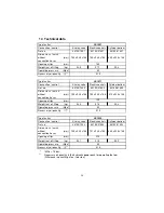
Страница 20: ...yp of cutter Connection control 4 3 way valve Electric controls Cylinder bottom Ref no 84150 1492 84150 91492 84150 81492 Dimensions l x w x h without connection hoses mm 755 x 235 x 168 754 x 235 x 1...

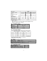
Страница 21: ...x 235 x 168 860 x 235 x 168 626 x 235 x 168 Opening at tips mm Weight incl oil filling kg 23 9 22 5 21 Operating pressure Mpa Necessary oil quantity l LSI 55 430 50 0 11 Range of oil temperature Visco...

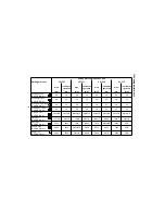
Страница 22: ...6 32 38 34 36 32 36 32 Round bar copper Rm 200 N mm 38 34 42 36 38 34 38 34 U profile steel Rm 500 N mm 50x40x5 40x25x5 60x40x6 60x25x6 65x45x6 60x40x5 65x45x6 60x40x5 Flat steel Rm 500 N mm 125x10 80...

Страница 23: ...advance with the LUKAS service department Type of cutter Testing pressure Operating pressure LSI 501 225 bar LSI 511 330 bar LSI 530 340 bar LSI 55 260 bar 50 MPa LSI5XX_BA_GB_841501490_0706 p65 Copyr...

Страница 24: ......

Страница 25: ......

Страница 26: ......

Страница 27: ......

Страница 28: ......

Страница 29: ......

Отзывы: