background image

22

 11.1  General information

The LUKAS hydraulic unit P 630 OG requires very little maintenance. For 

service work,


special illustrations are unnecessary; however, knowledge about the function of the unit, 

the legal safety instructions and dealing with the required tools are basic prerequisites.

ATTENTION!

Never use unnecessary force during maintenance work that could damage the 

components of the unit or compromise operational safety.

For safety reasons (high-pressure pump), 

service work

 on the hydraulic unit may 

only be executed by the equipment manufacturer, personnel trained by the equipment 

manufacturer or authorised LUKAS dealers.

WARNING / CAUTION / ATTENTION!

Protective  clothes  must  be  worn  when  maintenance  and  repairs  are  being 

carried out, since the devices may also be pressurised when not in operation.

During work, ensure that all components are particularly clean, since dirt can 

damage the rescue equipment!

11.Maintenance and repair

ATTENTION!

As  LUKAS  hydraulic  units  are  designed  for  top  performance,  only  those 

components in the replacement parts lists for the relevant unit can be replaced.

Further components in the unit may only be replaced if:

-  You have participated in an appropriate LUKAS service training course.

-  You have the express permission of LUKAS customer service (permission will 

be verified on request. To be checked in each individual case!)

When cleaning units and equipment, note that no cleaning agent may be used 

that has a pH value outside the range 5 - 8!

ATTENTION!

Attention must be paid to ensuring that no operating fluids escape from the 

units during repair work! 

Содержание P 630 OG

Страница 1: ...175077085 EN Hydraulic power unit P 630 OG Translation of the original instruction manual replaces 11 2014 Instruction manual for rescue equipment Edition 02 2017 ...

Страница 2: ... General information 10 5 2 Installation of the unit 11 5 3 Engine 12 5 4 Connecting block with mono coupling 13 5 5 Pump 13 6 Connecting the hoses devices 14 7 Erection and start up 16 7 1 Set up 16 7 2 Start up 16 8 Operation 18 8 1 Starting the engine 18 8 2 Stopping the engine 18 8 3 Refuelling 19 8 4 Controlling the valves 19 ...

Страница 3: ... 1 General information 22 11 2 Service work on the hydraulic unit 23 11 3 Additional service work 24 12 Fault analysis 30 13 Technical data 35 13 1 Unit 35 13 2 Noise emissions 37 13 3 Spark plug 38 13 4 Spark plug spanner 38 13 5 Fuel 38 13 6 Engine oil 39 13 7 Hydraulic fluid recommendation 39 13 8 Operating and storage temperature ranges 39 14 EC Declaration of Conformity 40 15 Notes 41 ...

Страница 4: ...or severe injury WARNING Potentially dangerous situation Potential death or serious injury CAUTION Less dangerous situation Minor or slight injury Property ATTENTION Danger of damage to property environment Damage to the equipment damage to the environment damage to surroundings NOTE Handling tips and other important useful information and advice No injury damage to persons environment device Wear...

Страница 5: ...NG CAUTION You must also observe the operating instructions for the hoses the accessories and the connected devices Even if you have already received instructions on how to use the equipment you should still read through the following safety instructions again WARNING CAUTION Ensure that the accessories and connected equipment are suitable for the maximum operating pressure Please ensure that no b...

Страница 6: ...ing on starting up the device and during its operation that this will put no one in danger Observe all intervals for recurring tests and or inspections that are prescribed or stated in the operating instructions When working close to live components and cables suitable measures must be taken to avoid current transfers or high voltage transfers to the equipment Only original LUKAS accessories and s...

Страница 7: ...s hydraulic fluid can be detrimental to health if it is swallowed or its vapour is inhaled Direct contact with the skin must be avoided for the same reason Also when handling hydraulic fluid note that it can negatively affect biological systems When working with or storing the equipment ensure that the function and the safety of the equipment are not impaired by the effects of severe external temp...

Страница 8: ...ufacturer supplier is not liable for any damage resulting from inappropriate use The user bears sole responsibility for such use Appropriate use includes observance of the operating instructions and compliance with the inspection and maintenance conditions Never work in a fatigued or intoxicated state WARNING CAUTION ATTENTION However if you still injure yourself on the hydraulic unit clean the wo...

Страница 9: ... limited The sum of the maximum required operating volume hydraulic fluid of all connected equipment may not exceed the maximum possible usable volume of the unit NOTE Always register your hydraulic unit on the LUKAS Hydraulik GmbH internet site This is the only way to guarantee your extended warranty cover Before you use couplings from a different company you must contact LUKAS or an authorised d...

Страница 10: ...oline engine and single flow operation All LUKAS rescue devices can be operated with the standard factory hydraulic fluid filling of 1 7 l 0 45 gal US An exception applies however for the following rescue rams R 422 and LTR 12 705 EN R 424 and LTR 12 875 EN R 430 and LTR 3 5 820 EN Before using any one of these cylinders you should fill the hydraulic oil reservoir up to the top level mark of the f...

Страница 11: ...ng handle swivelling 7 Cable starter 8 Mono coupling socket 9 Fuel filler cover 10 Filler cover for hydraulic fluid 11 Base 12 Rubber buffer 13 Air filter 14 Choke 15 Fuel tap 16 ON OFF switch engine switch 17 Engine oil filler cap dipstick 18 Fill level indicator 19 Silencer protection 20 Spark protection Equipment rear 17 16 18 6 7 11 13 14 15 19 16 5 20 ...

Страница 12: ... the engine described in the manufacturer s separate operating instructions Nevertheless it is important that you follow all safety rules and operating maintenance and storage instructions in the separate engine instructions as given as they are not affected by adjustments made by LUKAS The HONDA engines have a main switch that must be activated to switch the unit on and off The speed adjustment l...

Страница 13: ...l connected rescue equipment The LUKAS hydraulic unit P 630 OG comes equipped with a single flow pump The pump is rigidly connected to the connecting block Single flow pump for operating with rescue equipment The pump used always has two pressure stages one low pressure and one high pressure Low pressure level LP up to 14 MPa High pressure level HP up to 70 MPa The changeover from low pressure to ...

Страница 14: ...make sure that all the components used are suitable for the maximum operating pressure of the hydraulic unit In cases of doubt consult LUKAS directly before connecting the equipment 6 Connecting the hoses devices Plug Socket Dust protection caps The hose assemblies equipment are connected via quick disconnect coupling halves female and male to the hydraulic pump or hose reel in such a way that the...

Страница 15: ...nt is not turned on NOTE We recommend connecting the coupling halves in a depressurised state when working in areas with low ambient temperature and using extension hose assemblies hose reels as otherwise the coupling may require the application of a great deal of force For dust protection the supplied dust caps must be refitted Using the dust protection caps The dust protection caps A have two ex...

Страница 16: ...sioning or after longer periods of storage First fill the engine or top up with engine oil For safety reasons LUKAS units do not contain engine oil upon delivery 7 2 1 First commissioning Unit without engine oil and gasoline 1 Pour in the engine oil according to the instructions in the scope of delivery included with the separate manufacturer operating instructions regarding the filler opening eng...

Страница 17: ...comes out from the screw If necessary tilt the pump further The filling level should be between MIN MAX when the unit is in a horizontal position For filling level see illustration below 7 If oil comes out at the venting screw the air has escaped out of the pump First close the venting plug and then return the unit to level 8 Check the fluid levels again Top up if necessary 9 Now connect the exten...

Страница 18: ...witching position B choke when starting from cold 4 Pull starter cable 5 When the engine is running switch the lever back to position A For the detailed procedure for starting the combustion engine please see the separate operating instructions of the engine manufacturer B A 8 1 Starting the engine 8 Operation 1 Set the ON OFF switch to the OFF position 2 When the engine has come to a standstill c...

Страница 19: ...ure 1 Open the fuel tank cap 2 Pour fuel into the tank up to the lower edge of the fuel level indicator i e the convex edge below the filler opening 3 Close the fuel tank again with the fuel tank cap WARNING CAUTION ATTENTION Be sure not to spill fuel In particular hot engine parts must not come into contact with fuel danger of fire otherwise If fuel is spilled it must be cleaned up immediately wi...

Страница 20: ... international regulations with regard to the maintenance intervals of rescue equipment Operating time per day In the Federal Republic of Germany regular safety inspections according to the regulations of the Gesetzlichen Unfallversicherung GUV connoted Legal accident insurance are mandatory ATTENTION Clean off any dirt before checking the device WARNING CAUTION ATTENTION To perform inspections ma...

Страница 21: ...quired accessory parts e g spark plug spark plug spanner and fuel can are present Function test Unconventional or noticeable noises heard during operation Cable starter fully functional Engine switch switch lever and couplings fully functional Test for maximum load 10 2 Visual and function check Operating time per day Function test up to 1 hour 1 x annually up to 8 hours 1 x per quarter up to 24 h...

Страница 22: ...hen maintenance and repairs are being carried out since the devices may also be pressurised when not in operation During work ensure that all components are particularly clean since dirt can damage the rescue equipment 11 Maintenance and repair ATTENTION As LUKAS hydraulic units are designed for top performance only those components in the replacement parts lists for the relevant unit can be repla...

Страница 23: ...eployments but after three years at the latest replace the hydraulic fluid The fluid should be replaced after it has warmed up The engine must be switched off The used hydraulic fluid must be disposed of properly Replacing the hydraulic fluid procedure A B 5 Pour the new hydraulic fluid through the filler opening B into the hydraulic tank and close the neck again with filler cap B 6 The unit then ...

Страница 24: ...e the engine oil You must conduct the following service measures every 100 operating hours Check the spark plug clean if necessary set the electrode gap of the spark plug Clean the spark protector You must conduct the following service measures every 300 operating hours or every 2 years Replace the spark plug The following service work should be executed by an authorised dealer LUKAS directly or t...

Страница 25: ... excess oil If too much oil remains the engine will smoke when starting it 3 Wipe any dirt off the air filter housing and cover using a moistened cloth Ensure that dirt does not penetrate the carburettor NOTE Keeping the air filter in good condition and clean is extremely important Penetrating dirt leads to damage and wear in the engine in case of incorrect installation incorrect damage or unsuita...

Страница 26: ...ng the thread 6 Tighten the spark plug after mounting with a 5 8 inch spark plug spanner in order to compress the washer 7 A new spark plug should be tightened by an additional 1 2 turn after mounting in order to compress the washer 8 A used spark plug should be tightened by an additional 1 8 to 1 4 turn after mounting in order to compress the washer 9 Place the spark plug connector onto the spark...

Страница 27: ...g the spark protector 1 Remove the three 5 mm screws from the silencer and remove the silencer protector 2 Remove the special screw from the spark protector and remove the spark protector from the silencer Cleaning and inspecting the spark protector 1 Brush off any oil carbon deposits from the spark protection strainer using a suitable cleaning brush Ensure that the strainer is not damaged Replace...

Страница 28: ...Replacing the hydraulic fluid 2 Remove screwed fittings on the coupling 3 Remove couplings and underlying seals 4 Position the new coupling together with the seals on the valve block 5 Re attach the couplings with the bolts and tighten to a torque of MA 40 Nm 6 The hydraulic fluid tank must then be refilled and the unit vented 3 Loosen the union nuts on the hose assemblies and remove the coupling ...

Страница 29: ...s connected to connection T on the mono coupling 4 Position the new coupling and tighten the union nuts on the hose assemblies to a torque of MA 40 Nm and push the kink protection of the couplings back 5 The hydraulic fluid tank must then be refilled and the unit vented ...

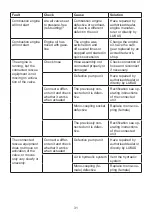
Страница 30: ...t engine switch to Choke Hydraulic unit or engine not suit able for the work ing environment Ambient temperature too low For the solution consult the separate operating instruc tions of the engine manufacturer Use a different hydraulic fluid or operating fluid that is suitable for the relevant ambient temperature see Chapter Technical Data Not enough oxygen in the air because of the altitude of ap...

Страница 31: ...ion of hose and reconnect if necessary Defective pump unit Have repaired by authorised dealer or directly by LUKAS Connect a differ ent unit and check whether it works when actuated The previously con nected unit is defec tive Rectification see op erating instructions of the connected unit Mono coupling socket defective Replace mono cou pling female The previously con nected unit is defec tive Rec...

Страница 32: ...t reached Have the pressure limiting valve reset or repaired by authorised dealer or directly by LUKAS Pump block defective Have repaired by authorised dealer or directly by LUKAS Connected unit defec tive Rectification see op erating instructions of the connected unit During function test A pressure gauge installed between the rescue equipment and the hydraulic unit does not indicate the maximum ...

Страница 33: ... bearing Radial shaft seal on the drive shaft is defective Have repaired by authorised dealer or directly by LUKAS Hydraulic fluid milky and cloudy Water condensation in the system Replace the hydraulic fluid immediately Hoses cannot be coupled Pressure too high e g caused by ambi ent temperature too high Switch valve block to circulation at static pressure Coupling defective Coupling must be repl...

Страница 34: ...ress for the LUKAS Customer Service department is LUKAS Hydraulik GmbH A Unit of the IDEX Corporation Weinstrasse 39 D 91058 Erlangen Tel 49 09131 698 348 Fax 49 09131 698 353 NOTE In case of faults which affect the combustion engine please also observe the instructions in the separate operating instructions of the engine manufacturer ...

Страница 35: ...ng quantity of the hydraulic tank results from the operability at a slant prescribed in the standards Because all values are subject to tolerances there may be small differences between the data for your device and the data in the following tables The values may also differ because of reading inaccuracies and or tolerances in the measuring equipment used 13 1 Unit 13 1 1 Basic dimensions of the un...

Страница 36: ...ate HD 1 l min 1 x 0 7 gal US min 1 x 0 19 Feed rate ND 2 l min 1 x 3 2 gal US min 1 x 0 85 Maximum operating pressure HD 1 MPa 3 70 psi 10000 Maximum operating pressure ND 2 MPa 3 14 psi 2000 Maximum filling volume and usable quantity hydraulic fluid l 3 1 7 gal US 0 79 0 45 Maximum filling volume gasoline l 0 77 gal US 0 17 Weight with gasoline and hydraulic fluid kg 15 9 lbs 35 1 Valve variants...

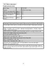
Страница 37: ...rement uncertainty KpA in dB 4 Measured A valued emission sound power level if required LWA in dB based on 1 pW 98 Measurement uncertainty KpA in dB 4 Determine values according to EN 13204 Appendix B using basic standards EN ISO 3744 and EN ISO 11201 NOTE The sum of the measured noise emission values and the associated measure ment uncertainty that can occur during the measurement represent the u...

Страница 38: ...8 13 3 Spark plug 13 5 Fuel Spark plug type CR5HSB NGK U16FSR UB DENSO Fuel Lead free gasoline ROZ 91 to ROZ 98 13 4 Spark plug spanner Universal joint spark plug spanner with spanner size 16 mm 5 8 inch ...

Страница 39: ... C HM 10 VG 10 Oil temperature range Oil code Viscosity rating Remarks A 4 0 131 F HM 10 VG 10 Recommended range of viscosity 10 200 mm s 10 200 cSt Supplied with HM 10 DIN ISO 6743 4 ATTENTION Before you use hydraulic fluids from a different manufacturer you must contact LUKAS or an authorised dealer Operating temperature C F 20 55 4 131 Storage temperature device not in operation C F 30 60 22 14...

Страница 40: ...40 14 EC Declaration of Conformity ...

Страница 41: ...41 15 Notes ...

Страница 42: ...42 ...

Страница 43: ...43 ...

Страница 44: ...opyright 2017 LUKAS Hydraulik GmbH P630OG_manual_175077085_en indd Subject to amendment Please duly dispose of all packaging materials and removed items WARNING CAUTION ATTENTION Before connecting the equipment make sure that all the components used are suitable for the maximum operating pressure of the hydraulic unit In cases of doubt consult LUKAS directly before connecting the equipment ...

Отзывы: