Chapter 10 Built-in PID Functions
10 - 23
10.7 How to Use PID Instructions
This section describes how to use PID instructions.
For detailed description of the functions of the CPU, specific modules and XG5000, refer to the corresponding
manuals.
10.7.1 Hardware configuration
The example system has a configuration as shown below.
Driver
(1) CPU (XGK-CPUH)
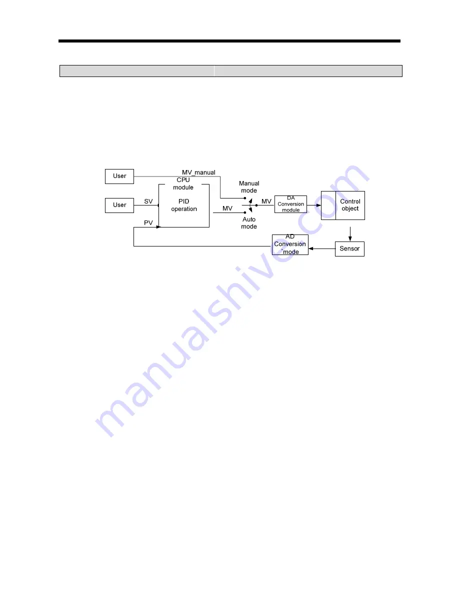
The CPU is where PID operation occurs and so can be called “PID controller”. The controller receives data
sensed from the input module, calculates a proper output through operation, and then transfers it to the
output module. What the user should do is to connect input and output and design the interior of the PID
controller (tuning). Generally, analog input module and analog output modules are used for input and
output, respectively.
(2) Analog Input Module (XGF-AV8A)
This functions to receive the state of the control object from the sensor and transfer it to the CPU. The
analog input module channel 0 enables to receive a voltage of 0 V ~ 5 V as input and transfer its digital
value to the PLC as output. There are 8 channels (CH 0 ~ CH 7) in XGF-AV8A. The setting for XGXGF-
AV8A can be changed through the I/O parameter setting window that appears when selecting I/O
Parameter from the parameter items in the project window. Channel 0 is changed to “Operation” mode and
the input range is set to 0 ~ 5 V (according to the sensor). The output data type is the PV value of the PID
controller. For PID control, the range of its value is set to 0 ~ 10000.
The 0 ~ 5 V signal detected from the sensor during analog input module operation is converted 2,000
times to a digital value of 0 ~ 10000 and then transferred to the PLC.


