background image

Ratings - Standard Ambient Models


(Continued)

MODEL

Leaving 

Chilled 

Liquid

˚C

Condenser Air Entering Temperature 

˚C


25

30

35

40

46

50

cool

Power

cool

Power

cool

Power

cool

Power

cool

Power

cool

Power

KW

KW

KW

KW

KW

KW

KW

KW

KW

KW

KW

KW

SA170

4.5

571 

159 

547 

171 

547 

179 

501 

177 

477 

227 

445 

236 

5

576 

159 

553 

170 

554 

180 

506 

178 

485 

229 

451 

238 

6

596 

162 

571 

173 

571 

182 

524 

180 

501 

232 

468 

242 

7

614 

166 

591 

177 

591 

187 

541 

184 

519 

234 

485 

246 

10

673 

175 

649 

185 

650 

196 

596 

194 

574 

248 

539 

259 

12

711 

180 

685 

192 

689 

203 

631 

200 

607 

257 

572 

268 

15

768 

187 

739 

198 

742 

211 

681 

209 

655 

268 

617 

278 

SA210

4.5

718 

188 

688 

201 

653 

213 

629 

222 

580 

276 

534 

288 

5

724 

189 

695 

202 

659 

214 

635 

223 

586 

276 

540 

289 

6

749 

192 

718 

204 

682 

216 

658 

228 

606 

281 

565 

292 

7

773 

197 

741 

208 

704 

221 

680 

232 

628 

287 

587 

299 

10

846 

206 

814 

219 

775 

233 

750 

243 

694 

302 

651 

315 

12

895 

214 

862 

228 

820 

241 

793 

251 

734 

313 

692 

325 

15

965 

221 

929 

236 

886 

250 

856 

262 

820 

323 

749 

338 

SA270

4.5

992 

241 

952 

257 

905 

294 

873 

287 

809 

360 

782 

374 

5

1004 

242 

962 

257 

913 

296 

882 

288 

817 

363 

791 

378 

6

1038 

245 

993 

261 

944 

300 

912 

292 

845 

367 

818 

383 

7

1070 

250 

1029 

266 

975 

307 

942 

298 

876 

374 

849 

392 

10

1172 

263 

1129 

279 

1074 

322 

1039 

314 

969 

395 

944 

411 

12

1240 

272 

1194 

287 

1136 

333 

1099 

324 

1025 

408 

1003 

424 

15

1339 

367 

1289 

298 

1226 

347 

1187 

337 

1105 

423 

1082 

442 

SA320

4.5

1091 

288 

1047 

304 

994 

323 

947 

344 

878 

434 

849 

452 

5

1102 

290 

1056 

306 

1003 

325 

956 

346 

887 

437 

857 

455 

6

1138 

295 

1091 

311 

1038 

330 

990 

351 

916 

443 

888 

462 

7

1175 

302 

1128 

318 

1070 

338 

1021 

359 

950 

448 

921 

471 

10

1286 

317 

1238 

334 

1179 

354 

1126 

377 

1050 

475 

1023 

495 

12

1360 

356 

1311 

345 

1247 

367 

1193 

390 

1110 

491 

1087 

512 

15

1468 

371 

1416 

359 

1347 

381 

1287 

404 

1199 

511 

1173 

532 

Note

:

 1. Standard models are designed for operation in ambient temperatures up to 46˚c (115 ˚F). When ambient temperatures rise above 


     46˚c compressors will progressively unload to prevent trips on high pressure/temperature/current.


2. Fouling factor of evaporator is 0.086 m2.·k/kW.


3. Specification may be changed without further notification


4. The unit conforms to standard ARI 550/590-98.


5. The cooling capacity and power supply is measured with the economizer.


6. Power consumption values include compressors and fans. 

LS


Air-Cooled Water Chillers 

11

Содержание SA075

Страница 1: ...R134a 75 to 350 RT A i r C o n d i t i o n i n g S y s t e m Air Cooled Screw Chiller ...

Страница 2: ...e solenoid valves sight glass moisture indicators and electronic expansion valves Inspection When the equipment is received all items should be carefully checked against the bill of lading to ensure a complete shipment All units should be carefully inspected for damage upon arrival The unit s serial plate should be checked before unloading the unit to be sure that it agrees with the power supply a...

Страница 3: ...e accessible housing ensuring the minimum levels of noise breakout and vibration This rugged structure ensures stable and reliable operation in ambient temperatures ranging from 15 to 55 c Cooler All SA liquid chillers are fitted with a single cooler of the Flooded shell and tube type having refrigerant in the shell and chilled water inside the tubes The shell is of welded alloy steel construction...

Страница 4: ...essed and formed aluminum alloy fan blades mechanically attached to rustless steel fan hubs Fan motors are waterproof rated to IP 54 with class F insulation suitable for operation in temperatures from 20 c to 65 c 4 F to 150 F Electronic Expansion Valve This is a standard feature on each refrigeration circuit on all Model SA liquid chillers Electronic expansion valves ensure stable operation throu...

Страница 5: ...p to four additional Slave chillers to optimize chiller running hours and energy consumption Multi compressor Option Models SA125 and SA150 are also available with 2 compressor and refrigeration circuits ESD Energy Saving Drive Reduce Energy Use The energy saving drive ESD technology revolutionized the performance of air cooled chillers ESD is a complete and high quality device with a variable fre...

Страница 6: ...ins Chilled water cooler Type Shell and tube high efficiency heat exchanger Water side working pressure Kg Sq cm 14 Nominal flow m h 46 59 1 76 89 1 104 2 118 1 135 1 152 158 4 177 2 194 1 213 Water resistance kPa 50 50 55 55 55 60 58 60 60 65 65 65 Water pipe diameter DN 100 100 125 125 150 150 150 150 150 200 200 200 Refrigerant Type R134a Charge Circuit kg 165 220 275 330 185 185 210 210 210 23...

Страница 7: ... Chilled water cooler Type Shell and tube high efficiency heat exchanger Water side working pressure Kg Sq cm 14 Nominal flow m h 45 1 61 2 79 3 91 7 104 2 122 4 139 6 147 7 158 6 180 9 199 9 212 7 Water resistance kPa 50 50 55 55 58 58 58 60 60 65 65 65 Water pipe diameter DN 100 100 125 125 150 150 150 150 150 200 200 200 Refrigerant Type R134a Charge Circuit kg 130 215 250 300 175 175 185 185 2...

Страница 8: ... 622 152 596 162 566 172 545 182 492 214 458 199 7 662 158 636 168 603 178 582 188 520 226 492 206 10 725 166 698 177 664 188 642 198 582 233 547 217 12 767 172 739 183 702 194 680 205 616 240 581 224 15 827 178 797 189 759 202 733 213 665 249 627 233 SA170 5 689 185 660 197 662 208 604 206 579 264 539 275 7 704 192 675 204 645 216 626 213 608 274 579 285 10 724 202 694 214 677 227 642 224 626 287...

Страница 9: ...33 467 SA300 5 1243 307 1191 323 1131 343 1077 365 1000 460 966 479 7 1325 319 1272 335 1206 356 1152 379 1034 452 1038 497 10 1450 334 1396 353 1329 374 1269 398 1184 501 1154 522 12 1534 376 1477 364 1406 387 1345 411 1252 518 1226 540 15 1656 391 1596 379 1518 402 1451 426 1352 539 1323 560 SA325 5 1380 384 1402 401 1429 417 1183 430 1109 446 745 457 7 1408 427 1430 446 1458 463 1207 477 1132 4...

Страница 10: ... 434 140 419 411 406 179 379 187 6 493 125 473 133 448 142 434 424 421 181 392 190 7 508 128 488 137 463 145 447 440 435 186 407 194 10 557 134 535 143 510 152 494 486 482 194 452 202 12 589 140 568 148 538 157 522 514 508 200 480 210 15 636 145 612 153 582 164 564 555 549 208 518 217 SA150 4 5 546 143 523 153 498 162 477 170 431 201 402 187 5 551 144 529 154 503 163 483 172 436 201 407 188 6 569 ...

Страница 11: ...3 296 882 288 817 363 791 378 6 1038 245 993 261 944 300 912 292 845 367 818 383 7 1070 250 1029 266 975 307 942 298 876 374 849 392 10 1172 263 1129 279 1074 322 1039 314 969 395 944 411 12 1240 272 1194 287 1136 333 1099 324 1025 408 1003 424 15 1339 367 1289 298 1226 347 1187 337 1105 423 1082 442 SA320 4 5 1091 288 1047 304 994 323 947 344 878 434 849 452 5 1102 290 1056 306 1003 325 956 346 8...

Страница 12: ...essure Drop Through Evaporator Line Symbol A SA075 SA100 B SA125 SA150 C SA170 SA210 D SA250 SA270 E SA300 F SA325 SA350 Water Pressure Drop Pressure Drop kPa Water Flow Rate l s LS Air Cooled Water Chillers 12 ...

Страница 13: ... 7 858 3 Standard Ambient Model 292 391 501 594 715 1 784 1 MODEL SA 225 250 270 300 325 350 Min Max Min Max Min Max Min Max Min Max Min Max Water Leaving Temp C 4 5 to 15 Cooling Range Entering Leaving C 3 to 20 Evaporator Flow Rate m3 h 49 138 53 155 48 159 55 188 57 200 64 220 Evaporator Pressure Drop kPa 15 122 18 128 18 128 21 134 21 134 22 138 MaximumWater side Pressure bar 10 Air Entering T...

Страница 14: ...ODEL Volts V Freq Hz System Compressor Fans RLA MCC Start Amps Qty RLA 170 380 50 l 161 271 403 6 5 ll 161 271 403 6 5 210 380 50 l 174 292 435 6 5 ll 174 292 435 6 5 225 380 50 l 174 292 435 6 5 ll 223 365 558 8 5 250 380 50 l 193 317 483 8 5 ll 223 365 558 8 5 270 380 50 l 223 365 558 8 5 ll 223 365 558 8 5 High ambient model SA MODEL Volts V Freq Hz System Compressor Fans RLA MCC Start Amps Qty...

Страница 15: ... 365 558 8 5 350 380 50 l 193 317 483 6 5 ll 193 317 483 6 5 lll 223 365 558 8 5 High ambient model SA MODEL Volts V Freq Hz System Compressor Fans RLA MCC Start Amps Qty RLA 300 380 50 l 256 317 640 6 5 ll 256 317 640 6 5 lll 256 317 640 6 5 325 380 50 l 256 317 640 6 5 ll 256 317 640 6 5 lll 327 404 818 8 5 350 380 50 l 295 365 738 6 5 ll 295 365 738 6 5 lll 327 404 818 8 5 Note RLA Rated Load A...

Страница 16: ...ressors and condenser fans are already running 5 Max running Amps values include compressors and fans Standard Model for 35 C Nominal Ambient Operation Electricity Supply 380 3 50 Model No Chiller Total Power Input Nominal Running Amps Maximum Running Amps Maximum Start Amps Nominal Kw Maximum Kw SA 75 82 9 124 4 150 8 292 0 392 4 SA 100 110 4 165 6 204 0 391 0 828 0 SA 125 145 1 217 7 262 4 501 0...

Страница 17: ...ning time of each compressor condenser assembly For multi chiller installations one unit can be selected as the master and its controller will sequence up to 4 slave chillers option Automatic and remote control of peripherals Remote start stop function via cabled connection On Off of chiller and system peripherals together with functional monitoring can be achieved through remote BMS System Time T...

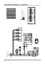
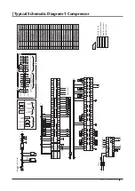
Страница 18: ...02 302 303 303 230 230 231 231 232 232 233 233 STARTER PNL CONTROL PNL BODY WIRING STOP SGL EMERGERNCY ABNORMAL SGL MOTOR POWER TRANSDUCER SGL CURRENT CONTACTOR SIGNAL COOLING FANS SIGAL FROM CONTROL PANEL TO CONTROL PANEL T2 T2 T2 R2 R2 R2 POWER CTRL PANEL 3 FROM TO CONTROL PANEL 2 THESE PARTS ARE LOCATED ON CHILLER BODY Note 1 THESE PARTS ARE LOCATED IN CONTROL PANEL ELECTRICAL PART LIST 1 1M 2M...

Страница 19: ...G FANS 29 MCCB MOLDED CASE CIRCUIT BREAKER 30 N F NOISE FILTER 31 F1 2 FUSE 32 V0 3 VARISTER 33 TR TRANSFORMER 34 EKD DRIVER MODULE ETS 35 EC ECONOMIZER SOLENOID VALVE 36 PB EMERGERNCY STOP SWITCH 120 OUT C0 Y0 Y1 Y2 Y3 Y7 Y6 Y5 DVP 08SN Y4 224 225 226 COM D24 1C 1B 1A TE01 2C 2B 2A TE02 3C 3B 3A 4C 4B 4A 5C 5B 5A TE05 COM D24 COM D24 24V G CH1 FG I L DVP 04PT L FG I L L L L I FG L L I FG CH2 CH3 ...

Страница 20: ...245 246 KM1 KM3 KM2 247 B B B MP 304 304 244 245 246 247 244 245 246 247 244 B B VP 124 D24 123 124 D24 E AIG AIG AIG AI6 AI6 AI6 AC2 AC1 R2 G IT A CT A AI5 T2 BC2 BC1 R2 G IT B CT B AI6 T2 3PH 380VAC 50 60HZ MAIN POWER SUPPLY 3PH 380VAC 50 60HZ MAIN POWER SUPPLY TO CONTROL PANEL 3 FROM TO CONTROL PANEL 2 THESE PARTS ARE LOCATED ON CHILLER BODY Note 1 THESE PARTS ARE LOCATED IN CONTROL PANEL START...

Страница 21: ...1 KM2 KM3 EC 235 236 B B B B A 240 241 242 243 PY SV1 SV3 SV2 244 245 246 247 FANS RUN SGL B B B B B 233 233 233 247 247 247 FAN FAN 1 2 3 R2 R02 R2 R02 R2 R02 PB E E E D24 D24 POWER 1PH 220VAC 50 60HZ TO ELEC EXP VALVE ETS A TO ELEC EXP VALVE ETS B FROM PLC TO PLC FOR CHW PUMP START STOP SGL FOR COMPRESSOR A RUN STOP INDICATION FOR COMPRESSOR B RUN STOP INDICATION FOR FAULT INDICATION FOR FAULT I...

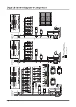
Страница 22: ...O CONTROL PANEL CONTACTOR SIGNAL A COOLING FANS SIGAL A STARTER PNL CONTROL PNL BODY WIRING ABNORMAL SGL B MOTOR POWER TRANSDUCER SGL CURRENT B TO CONTROL PANEL CONTACTOR SIGNAL B COOLING FANS SIGAL B 1 4 3 2 5 6 1 4 3 2 5 6 A 88F5 AU5 FM5 A A 51F5 AV5 AW5 A 88F6 AU6 FM6 A A 51F6 AV6 AW6 B 88F5 BU5 FM5 B B 51F5 BV5 BW5 B 88F6 BU6 FM6 B B 51F6 BV6 BW6 88F 2 A 322 51F2 A 324 51F4 A 88F 4 A 330 51F2 ...

Страница 23: ... B FROM STARTER PANEL CONTACTOR SIGNAL COOLING FANS RUN STOP TO STARTER PANEL 302 303 301 305 306 304 OUT C0 Y0 Y1 Y2 Y3 Y7 Y6 Y5 DVP 08SN Y4 OUT C0 Y0 Y1 Y2 Y3 Y7 Y6 Y5 DVP 08SN Y4 9C 9B 9A TE09 10B 10A TE10 COM D24 24V G CH1 FG I L DVP 04PT L FG I L L L L I FG L L I FG CH2 CH3 CH4 0V 10C 11C 11B 11A TE11 E 253 250 252 251 254 255 256 257 KM1 C KM2 C KM3 C EC C PY C SV1 C SV2 C SV3 C 260 261 262 ...

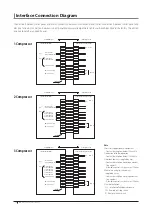
Страница 24: ...P SIGNAL FOR FLAUT INDICATION RUN STOP INDICATION REMOTE RUN STOP SINGLE FOR COMPRESSOR REMOTE RESET SINGLE TERMINAL NOTE 2 NOTE 3 NOTE 4 101 D24 401 402 403 404 PU D24 SW 410 411 405 406 102 103 D24 RS LS SWORKING SCOPE USER SWORK SCOPE CHILLER CONTROL PANEL USER S AUX EQUIP CONTROL PANEL FOR CHILLEDWATER PUMP NOTE 1 START STOP SIGNAL FOR FLAUT INDICATION RUN STOP INDICATION REMOTE RUN STOP SINGL...

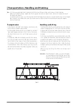
Страница 25: ...ith at least 15 meters of clear space in front of the container doors The chiller can then be pulled out of the container using 100mm diameter rollers under the base rails Once clear of the container the chiller can be lifted using hooks cables and spreader bars as shown below Handling and Lifting Care should be taken to avoid rough handling or shock due to impact or dropping the unit Do not push ...

Страница 26: ...Outline Dimensional Drawings SA075 Outline SA0125 Outline SA150 Outline SA170 SA210 Outline SA100 Outline LS Air Cooled Water Chillers 26 ...

Страница 27: ...Outline Dimensional Drawings Continued SA225 Outline SA250 SA270 Outline SA300 Outline SA325 SA350 Outline LS Air Cooled Water Chillers 27 ...

Страница 28: ...lacement of cooler tubes in case this repair is ever required The total space required for this operation is approximately half of the overall length of the chiller including the 2200mm shown in figure 2 Please contact factory for exact clearance dimensions When 2 or more chillers are placed side by side the distance between chillers must be a minimum of 3500mm and the distance between the opposit...

Страница 29: ...evel concrete pad the chiller should always be mounted on the neoprene anti vibration pads supplied loose with the chiller These pads are usually sufficient to prevent any lateral movement of the chiller on its foundation without the need for anchor bolts These pads will also effectively prevent the transmission of any slight noise or vibration from the chiller to its supporting structure For inst...

Страница 30: ...r square holes Base for square holes Base for square holes Base for square holes Base for square holes Base for square holes Base for square holes Base for square holes Base for square holes Base for square holes SA225 Foundation SA170 SA210 Foundation SA250 SA270 Foundation SA300 Foundation SA325 SA350 Foundation LS Air Cooled Water Chillers 30 ...

Страница 31: ...o permit isolation of the chiller for maintenance see figure 4 Flexible connections should be installed in supply and return chilled water piping to prevent the transmission of noise and vibration see figure 4 N B This is a mandatory requirement where the chiller is mounted on spring type AVMs anti vibration mountings External pipes and accessories should not be fixed t o the chiller unit and must...

Страница 32: ...compressor be checked with a vibration analyzer at or shortly after start up and again on an annual basis When performing the test the load should be maintained as closely as possible to the load of the original test The initial vibration analyzer test provides a benchmark of the compressor and when performed routinely can give a warning of impending problems Condensers The condensers are air cool...

Страница 33: ...g oil is charged into the chiller at the LS factory before testing and shipment of the finished chiller Under normal circumstances it will not be necessary to add to or replace this refrigerant and oil during the working life of the chiller If the chiller is damaged allowing refrigerant and or oil to leak out of the chiller then LS professional service technicians should be called in to identify a...

Страница 34: ...olled steel channel sections welded and bolted to form rigid load bearing framework to support all major unit components and safe lifting platform Frame shall be shot blasted after welding and finished with corrosion resistant primer and air drying epoxy based enamel Condenser coil frameworks cabinet and control center cabinet shall be of heavy gauge galvanised sheet steel with oven baked powder c...

Страница 35: ...eaving fluid temperature Evaporator and condenser pressure System refrigerant temperatures Chiller run hours Compressor run hours Compressor number of starts Compressor current Time of day Display module in conjunction with the microprocessor must 111 also be capable of displaying the output result of a service test Service test shall verify operation of every switch thermistor fan and compressor ...

Страница 36: ...g dong Dongan gu Anyang si Gyeonggi do Korea Tel 82 31 450 3531 3538 Fax 82 31 450 3540 Factory in China 266109 Yu Huangling Industrial Area Xiazhuang Chengyang District Qingdao China Tel 86 532 8096 5648 Fax 86 532 8096 5688 Distributed by Specifications subject to change without prior notice ACOS 01 2000 0901 Printed in Korea ...

Отзывы: