


General Information
12
ProtoMat M60
3.4 Installation
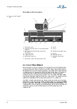
› Unpack the LPKF
ProtoMat
M60 carefully (for detaching the security
screws see Fig. 1 on page 12). Then loosen the transport safety
devices. These devices are marked red and are located:
• Locking of the X-axis - 2 aluminium elbow joints (safety device 2)
• Locking of the Y-axis - directly at the head to the left (safety
device 3)
• Locking of the Z-axis - Allen screw (safety device 4)
Note: The equipment must stand on a flat and firm base in order to
work properly!
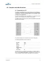
› Set up the circuit board plotter so that the connecting cables to the
electronic unit can move freely.
› Connect the LPKF
ProtoMat
M60 to the computer with the null
modem cable supplied with the system (COM1 or COM2).
› Plug the LPKF
ProtoMat
M60 control unit into the electricity supply
› Fit the Vacuum to the adapter (suitable for stay tube no. 111124 of a
Nilfisk industrial vacuum unit).
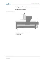
fig. 1: Transport safety devices of
the LPKF ProtoMat M60
Note: Keep all transport safety device and packing and mount them
accordingly if the machine is to be shipped.
1
- Attaching the machine safely to the transport support
2
- Securing the X-axis
3
- Securing the Y-axis
4
- Securing the mill/drill head
4


