1 2
→
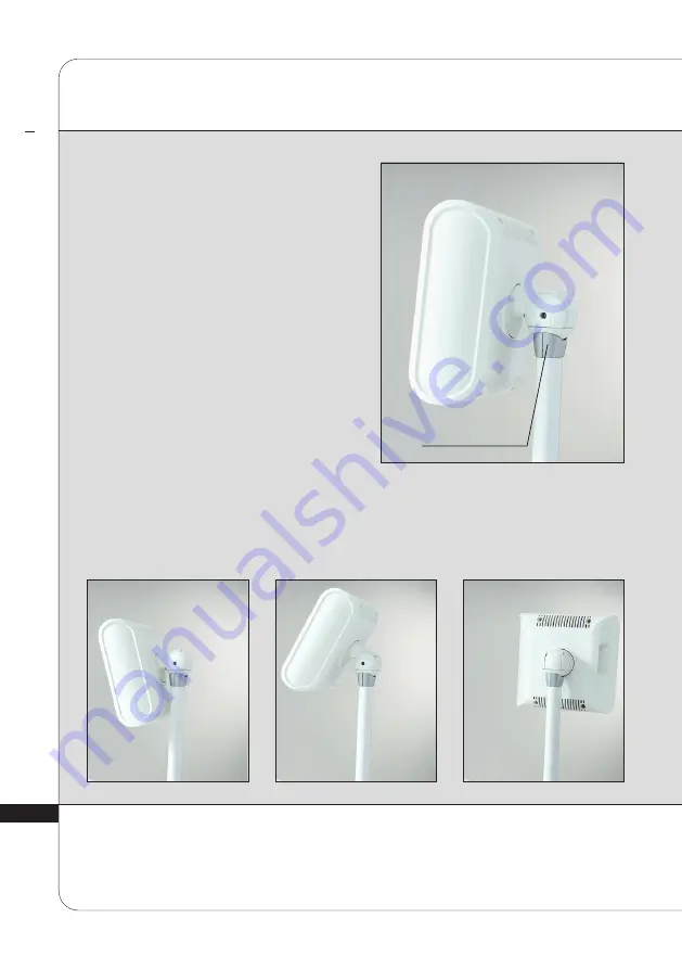
FRONT SIDE ADJUSTMENT
C
ONTR
OLS
DESCRIP
TION
2
The front side can be adjusted using the
articulated dial.
To adjust the front side, simply move it to
the desired position.
ARTICULATED DIAL
Страница 1: ...he complete manual carefully before using your equipment LPG Systems 2020 LPG Cellu M6 Endermolab KeymoduleTM and Endermowear are registered trademarks of LPG Systems and or trademarks on which it hol...
Страница 2: ...tment systems You will be able to fully appreciate the technical perfection and reliability that have made LPG Systems the leader in this field This operator s manual contains the operating descriptio...
Страница 3: ...ro nozzles micro heads One Ergolift head Two Ergolift TM chambers Lift 20 and Lift 10 One set of Lift heads One operator s manual Two electrical power cords One POS marketing set Depending on the vers...
Страница 4: ...3 3 Version 2 i Version i Version i B Ergodrive KM80 TR50 TR30 TR15 Micro nozzles Micro heads Ergolift Lift 20 Lift 10 Lift heads TML30 TML20 TML10 GU Power cords POS...
Страница 5: ...ibited All the illustrations in this operator s manual are non binding AT T E N T I O N TABLE OF CONTENTS 1 DEVICE DESCRIPTION 5 2 CONTROLS DESCRIPTION 7 3 SAFETY INFORMATION 15 4 MAINTENANCE 18 5 TRO...
Страница 6: ...fibrosis 12 Improve skin aging wrinkles fine lines skin sagging fat infiltration firmness elasticity complexion and eye bags 13 Stimulate fibroblasts collagen elastin and hyaluronic acid synthesis It...
Страница 7: ...on After switching on the unit please wait a few seconds for the screen to display information AT T E N T I O N CELLU M6 ENDERMOLAB CONT D D E V I C E D E S C R I P T I O N 1 ADJUSTABLE BACK HOSE HOS...
Страница 8: ...7 D E V I C E D E S C R I P T I O N 2 HEAD STORAGE TRAY AND DRAWER FILTER ACCESS HEAD STORAGE TRAY HEAD STORAGE DRAWER FILTER ACCESS DOOR THE FILTER IS ACCESSIBLE ON THE SIDE OF THE BOX...
Страница 9: ...anual received during training and available from customer service AT T E N T I O N QUICK CONNECT SETTING CONTROL BUTTONS CONTROL SCREEN TRIGGER BUTTONS TO REVERSE DIRECTION OF ROLLERS SETTING CONTROL...
Страница 10: ...9 C O N T R O L S D E S C R I P T I O N 2 TR50 HEAD ADAPTER QUICK CONNECT CONTROL SCREEN SELECTION BUTTONS ROLLERS SEALING VALVE HOLDER SELECTION BUTTONS QUICK CONNECT...
Страница 11: ...1 0 HEAD C O N T R O L S D E S C R I P T I O N 2 CONNECTION BETWEEN BOX AND TABLE...
Страница 12: ...k pull the handle on the adjustable back and then raise or lower the back while holding onto the handle The table height is adjustable using the controls on the table see photo to left Simply press th...
Страница 13: ...2 FRONT SIDE ADJUSTMENT C O N T R O L S D E S C R I P T I O N 2 The front side can be adjusted using the articulated dial To adjust the front side simply move it to the desired position ARTICULATED DI...
Страница 14: ...F The Cellu M6 Endermolab i device is equipped with a shelf to hold the different treatment heads This shelf can be moved along the length of the table by sliding it along the provided rail LINE FACIA...
Страница 15: ...C O N T R O L S D E S C R I P T I O N 2 STRAPS Your Cellu M6 Endermolab i device comes with a set of straps including one lateral strap and two longitudinal straps These straps should be set up as sh...
Страница 16: ...isconnect the device from the electrical supply if it is not going to be used for a long period Special attention is required while using the device with or in the proximity of children or disabled pe...
Страница 17: ...ifferential etc are always adapted to the cutaneous tissue being treated Do not put more than 135 kg on the table The controls used to adjust the height of the table can be inhibited if the cable is d...
Страница 18: ...s Do not treat patients with circulatory problems without first consulting their doctor Do not treat any swollen or inflamed areas without seeking medical advice and without having had training in spe...
Страница 19: ...ATING PLATE 19 CLEANING THE DEVICE 20 REPLACING THE FILTER CARTRIDGES AND FOAM 21 CONNECTING DISCONNECTING THE TREATMENT HEADS 23 DISCONNECTING THE BOX HOSE 24 CONNECTING DISCONNECTING THE ADAPTER 25...
Страница 20: ...before using your device This symbol indicates the name and address of the manufacturer VOLTAGE FREQUENCY AND POWER Your unit is identified by two serial numbers shown on the rating plates These rati...
Страница 21: ...m patient weight permitted on this equipment is 135 kg This symbol means always consult the accompanying documents before using your device It is recommended that you clean your unit as often as possi...
Страница 22: ...d the filter meter should be reset by pressing the icon indicated Fig 6 Ensure that the filter cartridge is changed as soon as the command screen displays one of these messages Fig 1 2 Icon indicating...
Страница 23: ...ge Open the filter access door Unscrew the filter cartridge and replace it with a new one Contact LPG Systems Customer Support to stock up on filter cartridges so that you always have spares Your devi...
Страница 24: ...ed position Fig 1 Position the end of the hose so that the hose key is lined up with the key slot of the treatment head connection Fig 2 Push the hose into the treatment head connection until it click...
Страница 25: ...e hose can be disconnected from the box simply by following the procedure described below Unlock the connection by turning the aluminum ring Fig 1 Lift the aluminum ring Fig 2 Gently remove the hose b...
Страница 26: ...MICRO HEAD CONNECTION LIFT HEAD CONNECTION To connect or disconnect the hose adapter follow the procedures below Only the auxiliary heads the micro nozzle tip and the Lift heads can be connected to t...
Страница 27: ...evice first connect each of the two power cords to their respective base C13 Plug to the table base C19 Plug to the box base Next connect each of other ends to a standard grounded electrical wall sock...
Страница 28: ...done when the warning message appears Replacement of Endermolift Kit To be done when the flaps no longer treat the skin properly They should be replaced after approximately every 14 hours of use DATE...
Страница 29: ...r cartridges clean and correctly placed Is the hose free of obstruction Is the hose properly connected Are the sealing valves of the main head correctly placed clean and moving Is the Keymodule of the...
Страница 30: ...e electrical features Operating environment Ambient temperature 10 C to 30 C for normal operation Ambient relative humidity 30 to 75 without condensation Atmospheric pressure no significant influence...
Страница 31: ...3 0 3 0 T R E A T M E N T H E A D S 7 TREATMENT HEADS...
Страница 32: ...T HEAD DESCRIPTION 39 TREATMENT CHAMBERS DESCRIPTION 39 lift heads description 40 micro nozzles and micro heads description 40 CLEANING THE ERGOLIFTtm HEAD AND ERGOLIFTtm CHAMBERS 42 CLEANING THE LIFT...
Страница 33: ...N T H E A D S 7 ERGODRIVETM HEAD DESCRIPTION QUICK CONNECT ROLLERS TREATMENT CHAMBER SELECTION BUTTONS CONTROL SCREEN TRIGGER BUTTON SELECTION BUTTONS KEYMODULE LOCK KEY LOCK CLIP KEYMODULE LOCK RING...
Страница 34: ...Ergodrive head It comprises the motorised rollers and sealing valves You have one KeymoduleTM set KM80 Installation The KeymoduleTM set is designed to be compatible with the treatment head Attach the...
Страница 35: ...sible to adjust the spacing between the motorised rollers When the slider is positioned to the left Fig 1 this allows the maximum level of mobility in the rollers When the slider is positioned to the...
Страница 36: ...Fig 1 2 The head can now rotate freely Fig 3 To lower the lock ring and lock the postion of the head press the lock key Fig 4 These four positions can be found by a following the preceding instructio...
Страница 37: ...E A D S 7 TR50 HEAD DESCRIPTION ROLLERS TREATMENT CHAMBER ROLLER LOCKING BUTTONS FORWARD LOCKING BUTTON REAR LOCKING BUTTON CONTROL SCREEN SELECTION BUTTONS TRIGGER BUTTON TO REVERSE DIRECTION OF ROL...
Страница 38: ...REAR ROLLER LOCKED NEAR FRONT AND REAR ROLLERS LOCKED NEAR REAR ROLLER LOCKED FAR Locking the rollers The rollers on the TR50 can be locked simply by pressing the appropriate buttons as shown in the p...
Страница 39: ...A T M E N T H E A D S 7 AUXILIARY HEADS DESCRIPTION ADAPTER DESCRIPTION ROLLER LOCKING MECHANISM ROLLERS ROLLERS TR 30 TR 15 POWER DECREASE BUTTON ON OFF BUTTON POWER INCREASE BUTTON TREATMENT MODE SE...
Страница 40: ...FT10 can be connected to the ErgoliftTM head They can be connected and disconnected by a simple push pull action Lift 10 Treatment chamber with removable flap SELECTION BUTTON FOR TREATMENT TYPE POWER...
Страница 41: ...ereby optimizing performance it is important to adjust the dial settings according to the treatment intensity Turn the dial from A to E to increase the flap s return force Turn the dial from E to A to...
Страница 42: ...must be given to the cleanliness of the parts that are in contact with the patient Before each use clean the flap and ErgoliftTM chamber 1 Disconnect the chamber from the ErgoliftTM treatment head Fi...
Страница 43: ...of three rinses 4 Dry the ErgoliftTM chamber and flap 5 Clean the storage drawer with antiseptic wipes then place the ErgoliftTM chamber and flap in it The use of aggressive products such as acetone...
Страница 44: ...to the opening between the flaps 2 Pull out the tool and the flaps will come out with it 3 Remove the flaps from the tool and clean them carefully with a wipe 4 Take the smooth side of the tool and pl...
Страница 45: ...the correct removal tool into the opening between the flaps 2 Pull out the tool and the flaps will come out with it 3 Remove the flaps from the tool and clean them carefully with a wipe 4 Take the smo...
Страница 46: ...Move the rollers to the center 3 Remove the corresponding sealing valve by handling it as shown on the photo Repeat the operation for the other valve Fig 2 4 Meticulously clean the flaps and their ho...
Страница 47: ...y to clean the entire surface Fig 2 c The sealing ring between the KeymoduleTM set and head housing d The plastic covering on the KeymoduleTM set 2 Turn the Keymodule again and refit the sealing valve...
Страница 48: ...ked in a bactericide and fungicide solution a Flaps and their housing Fig 5 and 6 b The casing on both sides of the rollers turn the head over rotate the rollers manually to clean the entire surface F...
Страница 49: ...4 8 T R E A T M E N T H E A D S 7 CLEANING THE TR50 HEAD CONT D FIG 7 FIG 5 FIG 9 FIG 8 FIG 6 FIG 10...
Страница 50: ...3 For the auxiliary heads use the dedicated tool provided Fig 3 to 4 4 Thoroughly clean for at least one minute the rollers seal treatment chamber micro heads disassembly tool and micro nozzles with...
Страница 51: ...ads micro nozzles and micro heads can be used directly on the skin in specific cases In these cases the heads need to be disinfected after each use 1 Use the cleaning procedure described above 2 Soak...
Страница 52: ...ring the treatment The Endermowear unique composition ensures an excellent grip of the skin for facilitating smoother movements of the treatment head as well as protecting it The products come with a...
Страница 53: ...partially completed will be rejected The appliance is guaranteed against manufacturing flaws and defects in the raw materials The warranty extends for the shorter of the following two periods two 2 ye...
Страница 54: ...ce Modification mounting of accessories or dismantling of the equipment Any operation and or intervention not specified in the LPG Systems Operating Instructions and performed on the equipment by the...
Страница 55: ...rchaser user is responsible for the use of the device and will assume full responsibility for any damages including damages caused to third parties resulting from the failure to observe the instructio...
Страница 56: ...5 5 W A R R A N T Y 9 WARRANTY ACTIVATION You can activate your warranty online by connecting to our warranty webpage http warranty lpgsystems com...
Страница 57: ...elds IEC 61000 4 3 10V m 80MHz 2 7 GHz 80 AM to 1 kHz 10V m 80MHz 2 7 GHz 80 AM to 1 kHz Proximity fields issued by RF wireless communication devices IEC 61000 4 3 Frequency MHz Modulation Requirement...
Страница 58: ...uld not be used adjacent to or stacked with other medical devices The Cellu M6 Endermolab i device does not manage essential performances Interference may occur near equipment marked with the followin...
Страница 59: ...ictement interdite Photos non contractuelles SI GE SOCIAL LPG SYSTEMS S A S TECHNOPARC DE LA PLAINE 30 RUE DU DR ABEL CS 90035 26902 VALENCE CEDEX 09 FRANCE TEL 33 0 4 75 78 69 00 FAX 33 0 4 75 42 80...