I271
I
GB
F
E
02
17
31100324
G
B
13
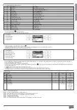
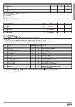
M10 - COUNTERS Default Range
P10.n.01 Count source OFF OFF-ON-INPx-LIMx-BOOx
P10.n.02 Channel number (x) 1 1-8
P10.n.03 Multiplier 1 1-1000
P10.n.04 Divider 1 1-1000
P10.n.05 Counter description CNTn (Text - 16 chars)
P10.n.06 Unit of measure Umn (Text - 6 chars)
P10.n.07 Reset source OFF OFF-ON-INPx-LIMx-BOOx
P10.n.08 Channel number (x) 1 1-8
Note:
This menu is divided into 4 sections, for counters CNT1..4
P010.n.01
= Signal that causes the increment of the counter (on rising edge). It can be the power-on of the multimeter (ON), the overcoming of a limit threshold (LIMx), the activation of an external input (INPx), one
logic combination (BOOx).
P010.n.02
= Number of the channel (x) referred to previous parameter.
P010.n.03
= Multiplying factor. The pulse count is multiplied by this coefficient before being displayed.
P010.n.04
= Dividing factor. The pulse count is divided by this coefficient before being displayed. If different from 1, then the value is displayed with 2 decimals.
P10.n.05
= Description of the counter. Free text 16 characters.
P10.n.06
= Unit of measure of the counter. Free text 6 characters.
P10.n.07
= Signal that causes the clearing of the counter. As long as this signal is activated, the counter remains at value 0.
P10.n.08
= Number of the channel (x) referred to previous parameter.
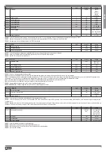
M11 - PULSES Default Range
P11.n.01 Measurement source kWh+ kWh+,kWh-,kvarh+,kvarh-,kVAh
P11.n.02 Count unit 100 10/100/1k/10k
P11.n.03 Pulse duration 0.1 0.01-1.00
Note:
This menu is divided into 5 sections, for energy count pulses PUL1..5
P11.n.01
= Type of energy to which the pulse is linked to.
P11.n.02
= Quantity of energy for each pulse. (e.g. 10Wh, 100Wh, 1kWh, etc.).
P11.n.03
= Pulse duration.
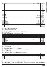
M12 - BOOLEAN LOGIC Default Range
P12.n.01 Operand 1 OFF OFF-LIMx-INPx-OUTx-REMx-BOOx
P12.n.02 Channel number (x) 1 1 - 8
P12.n.03 Logic operator 1 - - - - - - - AND - OR - EXOR - AND NOT -
OR NOT - EXOR NOT
P12.n.04 Operand 2 OFF OFF-LIMx-INPx-OUTx-REMx-BOOx
P12.n.05 Channel number (x) 1 1 - 8
P12.n.06 Logic operator 2 - - - - - - - AND - OR - EXOR - AND NOT -
OR NOT - EXOR NOT
P12.n.07 Operand 3 OFF OFF-LIMx-INPx-OUTx-REMx-BOOx
P12.n.08 Channel number (x) 1 1 - 8
P12.n.09 Logic operator 3 - - - - - - - AND - OR - EXOR - AND NOT -
OR NOT - EXOR NOT
P12.n.10 Operand 4 OFF OFF-LIMx-INPx-OUTx-REMx-BOOx
P12.n.11 Channel number (x) 1 1 - 8
Note:
This menu is divided into 8 sections, for Boolean variables BOO1..8
P12.n.01
= First operand of the Boolean logic.
P12.n.02
= Number of the channel (x) referred to previous parameter.
P12.n.03
= Logic operation between first and second operands.
P12.n.04
= Second operand.
From P12.n.05 to P12.n.11 – (as given above).
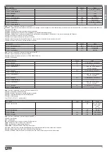
M13 - INPUTS UdM Default Range
P13.n.01 Input function OFF OFF - ON - LOCK -
SYNC - TAR-A -
TAR-B
C01...C08
P13.n.02 Normal status OFF OFF-ON
P13.n.03 ON delay sec 0.05 0.00 - 600.00
P13.n.04 OFF delay sec 0.05 0.00 - 600.00
Note:
This menu is divided into 8 sections, for digital inputs INP1..8
P13.n.01
= Input function:
OFF
– Input disabled
ON
– Input enabled, used as a source for counters, Boolean logic, etc.
LOCK
– Settings lock. Does not allow access to both levels.
SYNC
– Synchronisation for power/energy integration.
TAR-A, TAR-B
– Energy tariff selection. See Energy tariffs chapter.
C01…C08
– When this input is activated (edge-triggered), the corresponding command of the commands menu is executed.
P13.n.02
= Normal status of the input. Allows to invert the INPn activation logic.
P13.n.03 – P13.n.04
= Delay on activation – deactivation of the input. Allow to filter the input status to avoid bouncing.


