I6
0
4
G
B
I
0
9
1
9
3
1
1
0
0
4
4
2
3
WIRING TEST
– The wiring test allows to verify if the connection of the DMG5... device has been executed properly.
– To be able to execute the test, the device must be connected to an active plant, with the following conditions:
• three-phase system with all phases presence (V > 50VAC PH-N)
• current flowing in each phase > 1% of the CT primary.
• positive flow of energies (that is a normal plant where the inductive load draws power from the supplier).
– To launch test execution, enter command menu and select command C.16 as per Commands menu instructions.
– The test allows to verify the following points:
• reading of the three voltage phases.
• phase sequence.
• voltage unbalance.
• reverse polarity of each CT.
• mismatch between voltage and current phases.
– If the test does not succeed, the display shows the reason of the failure.
INSTALLATION
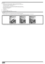
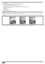
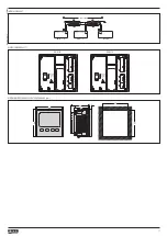
– DMG5... is designed for flush-mount installation. With proper mounting, it guarantees IP40 front protection.
– From inside the panel, for each four of the fixing clips, position the clip in one of the two sliding guide, then press on the clip corner until the second guide snaps in.
– Push the clip forward pressing on its side and making it slide on the guides until it presses completely on the internal surface of the panel.
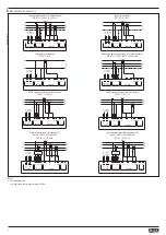
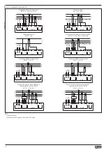
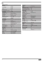
– For the electrical connection see the wiring diagrams in the dedicated chapter and the requirements reported in the technical characteristics table.


