


13
1. Secure the main engine and insert the output shaft into the hexagon hole of the transmission
countershaft in the lower part of the transmission box.
2. Installation of shaft and wheel: install the wheels onto both ends of output shaft and use 2 locking pin
assemblies to secure them.
4. Assembly of damping lever: fix the damping lever mount onto the damping lever fixing seat, use a
damping lever support pin to connect them, and insert a
Φ
3.5×
Φ
13×81 pin clip; then insert the damping
lever into the square groove of the damping lever mount and use a
Φ
12×40 axis pins and a
Φ
2.5×
Φ
9×46 pin
clips to secure them.
5. Installation of hand pipe assembly: align the tooth disc on the handrail frame to the handle pipe
adjusting tooth disc, take care to adjust the vertical position o the handle pipes, and use lifting handle and
handle adjusting nut to connect handle pipe assembly onto the handle pipe connecting seat and tighten it.
6. Installation of shift lever: insert the shift lever through the hole of the handle pipe connecting part’s
lug, and into the hole of the gear shift arm, and then use a
Φ
3.2
×
26 split pin to secure it. Put the shift lever
in the neutral position.
7. Refer to the illustrations of the mini tiller’s accessories for information about assembling of the mini
tiller.
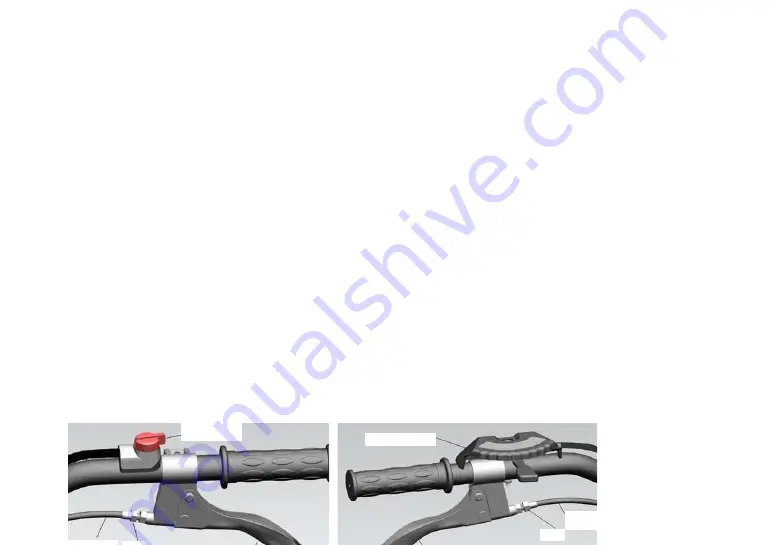
ii. Installation and adjustment of cables
1.
Adjustment of clutch cable (see Figure 2 and Figure 4).
2.
Reverse
cable
Nut
Accelerator handle
Start switch