


23
COMPILER TECO/ATI
ENDORSED
DATE
14.07.2003
REG. CODE
1-5302-616
MODEL N°
50898
DATE OF ISSUE
07-03
REVISION
00
X
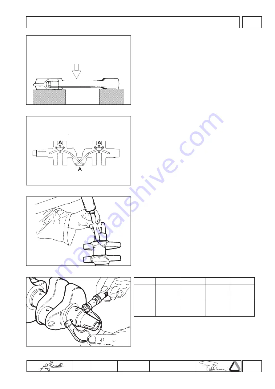
25
26
27
28
-0,50 mm
49,505
÷
49,515
44,494
÷
44,510
-0,75 mm
49,255
÷
49,265
44,244
÷
44,260
-0,25 mm
49,755
÷
49,765
44,744
÷
44,760
STD mm
50,005
÷
50,015
44,994
÷
45,010
A - B - D
C
CHECKS AND OVERHAUL
2. Position the calibrated pin on two prisms arranged on a check
surface.
3. Use a dial gauge to check that the discrepancy between
readings at the ends of the calibrated pin is no more than 0.05
mm; should deformation exceed this value (max. 0.10mm) the
connecting rod must be straightened.
This operation is performed by placing the connecting rod on a
parallel surface and applying slight pressure mid-way along the
convex side of the stem (fig.25).
Undersize bearing bushes are already available at the necessary
sizes without requiring any adjustment by boring.
Dimensions
Crankshaft
Whenever the engine is dismantled, particularly for the replacement
of cylinders and pistons due to wear caused by the aspiration of
dust, it is good practice to check the condition of the crankshaft.
1. Remove the plugs “A” from the oil passages (fig.26).
2. Use an appropriately shaped steel punch to clean the inside of
the oil passages and the collection traps. If the deposits are
particularly resistant, immerse the whole crankshaft in petrol or
paraffin before proceeding with the operations.
3. When the oil passages and traps have been throughly cleaned,
close the openings with new plugs (fig.27).
Checking crankshaft dimensions
Once the crankshaft has been thoroughly cleaned, use a
micrometer to check the wear and ovality of the main journals and
crank journals across two sections at right angles to each other
(fig.28).
If wear exceeds 0.08 mm (fig.29) grind the crankshaft to the
dimensions shown in the table:


