Logic Digital Controller
User Guide version 3
Page 9 of 31
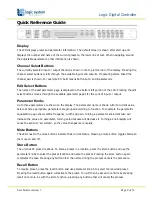
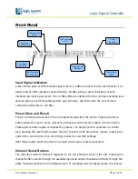
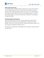
Front Panel
2x 24 character
LCD
Input Signal
Indicators
Store and
Recall buttons
Channel Select
buttons
Parameter Edit
Encoders
Output Mute
buttons
Limiter
Indicators
Edit Parameter
Select buttons
Input Signal Indicators
A set of three pairs of LEDs indicate signal present, +4dBu and input clip for each channel. The
signal present LEDs operate at approximately –40 dBu, giving a useful indication of even
relatively low input signal levels. The +4 dBu LEDs are intended to show nominal operating level
and can also be useful for setting system gain structure. Clip LEDs warn the user of input
overload and operate at +19 dBu.
Preset Store and Recall
These controls provide access to the 45 presets stored within the device. Pressing the store
button allows the user to name a preset and choose which memory location it will be held in.
Pressing store button again completes the process. The Recall function operates in a similar
way, pressing the recall button allows the user to select which preset they require, pressing the
button for a second time, then confirming, recalls the new DSP settings.
Note that presets cannot be stored or recalled when secure mode is activated.
Channel Select Buttons
The currently selected channel is displayed on the top left hand corner of the LCD. Pressing the
channel buttons scrolls through the available input and output channels and finally through the
utility functions and back to the default screen. If operating a stereo linked preset, the channel


