Owner’s Manual (Hydraulic Flail Mower)
N14800 3 - August, 2004
1
Maintenance
Lubrication:
The operation and component lifetimes of this
machine are very dependent on regular and proper
lubrication. The frequency of lubrication
recommended is based on normal conditions.
Severe or unusual conditions may determine actual
service requirements.
Replace any broken or missing grease fittings. Be
sure to clean fittings before greasing
.
NOTE:
Rotor, roller, and line shaft bearings
cannot be damaged by over-greasing. Grease
bearings until a small amount of grease is purged
from the bearing.
The following items require lubrication every (8)
hours of running time:
A)
Rotor bearings - located on each end of
machine and on the driveline side,
located under belt cover.
B) Roller bearings - located on each end of
roller.
C) Universal joint - located on left side of
the drive motor, under driveline shield.
The following items require lubrication every (25)
hours of running time:
A)
Belt idler bracket - located under belt
cover.
General Service
When reassembling components, always use new
lock nuts and a thread-locking compound to insure
against vibration loosening. Use an anti-seize
compound on all bearing/shaft contacts.
Procedure for Adjusting Height of Cut:
This procedure should be performed on a level
surface with mower mounted on tractor
.
The Loftness Flail Mower uses slotted adjustments
on the rear roller to allow an infinite cutting height
adjustment from 0 to 4-1/2”. To adjust the height
of cut:
1) Set bucket tilt cylinders to carry flail
mower level from front to rear.
2) Manually position knife rotor until the
bottom row of knives is at the lowest
operating position.
3)
Set blocks under skid shoes at the desired
cutting height.
4)
Loosen the nuts of the 5/8” carriage bolt
and the 5/8” pivot bolt, on both sides of
the mower.
5) Allow steel roller to contact ground.
6)
Retighten the (4) 5/8” nuts to 170 ft. lbs.
7) Remove blocks from under skid shoes.
8)
Adjust the skid shoes 1”- 2” from ground
to prevent scalping by means of the 1/2”
carriage bolts and the 1/2” pivot bolts.
9)
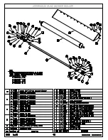
Refer to page 4-5 in Section 4 for an
illustrated parts listing.
Knife Reversal or Replacement:
When the knives become dull, they should be
reversed to extend the usable life. When both sides
of the knives become dull, the set must be replaced.
Always replace knives as a set (2), either when
broken or dull. If a set of knives is replaced, the set
on the opposite side of rotor must be replaced to
maintain the balance. (The knife mounts are
staggered and no set is directly across from another.
If the 3rd set of knives is replaced on one side,
replace 3rd set on opposite side, etc.).
1)
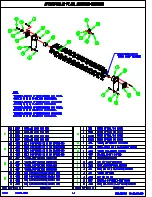
Refer to page 4-4 in Section 4 for an illustrated
parts listing.
2)
Remove the 9/16” standard nut , (2) flat
washers, the 9/16” bolt, and the set (2) of
knives.
3)
Install new knives or reversed set. (The bolt
must be inserted through the knife mount from
the left side in
in order for the nut to be tightened by rotation).
4) Make certain the bolt is forced to the outside of
the knife mount loop.
Содержание 48MH
Страница 4: ......
Страница 6: ......
Страница 9: ...Section 1 Safety ...
Страница 16: ......
Страница 17: ...Section 2 Operating ...
Страница 20: ......
Страница 21: ...Section 3 Maintenance ...
Страница 29: ...Section 4 Service Parts ...
Страница 30: ......
Страница 33: ......
Страница 34: ......
Страница 35: ......
Страница 36: ......
Страница 37: ......
Страница 38: ......
Страница 39: ......
Страница 40: ......
Страница 41: ......
Страница 42: ......
Страница 43: ......
Страница 44: ......
Страница 45: ......


