


Installation & Operation Manual
3
General venting
(continued)
23
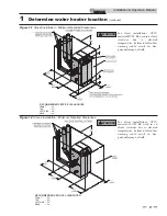
Vent, air piping and termination:
The Armor water heater vent and air piping can be installed
through the roof or through a sidewall. Follow the procedures
in this manual for the method chosen. Refer to the
information in this manual to determine acceptable vent and
air piping length.
If the water heater combustion air inlet is
located in a laundry room or pool facility, for
example, these areas will always contain
hazardous contaminants.
To prevent the potential of severe personal
injury or death, check for areas and products
listed in Table 1A, page 11 before installing
the water heater or air inlet piping.
If contaminants are found, you MUST:
• Remove contaminants permanently.
—OR—
• Relocate air inlet and vent terminations
to other areas.
WARNING
WARNING
Air contamination
Pool and laundry products and common household and hobby
products often contain fluorine or chlorine compounds. When
these chemicals pass through the water heater, they can form
strong acids. The acid can eat through the water heater wall,
causing serious damage and presenting a possible threat of flue
gas spillage or appliance water leakage into the building.
Please read the information given in Table 1A, page 11, listing
contaminants and areas likely to contain them. If
contaminating chemicals will be present near the location of the
water heater combustion air inlet, have your installer pipe the
water heater combustion air and vent to another location, per
this manual.
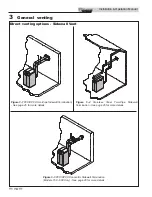
Optional room air
Commercial applications utilizing the Armor water heater
may be installed with a single pipe carrying the flue products
to the outside while using combustion air from the equipment
room. In order to use the room air venting option the
following conditions and considerations must be followed.
•
The unit MUST be installed with the appropriate
room air kit (Table 3F).
•
The equipment room MUST be provided with
properly sized openings to assure adequate
combustion air. Refer to the instructions provided
with the room air kit.
•
There will be a noticeable increase in the noise level
during normal operation from the inlet air opening.
•
Using the room air kit makes the unit vulnerable to
combustion air contamination from within the
building. Please review Section 1, Prevent
Combustion Air Contamination, to ensure proper
installation.
•
Vent system and terminations must comply with the
standard venting instructions set forth in this
manual.
NOTICE
Optional room air is intended for
commercial applications. Combustion air
piping to the outside is recommended for
residential applications.
WARNING
When utilizing the single pipe method,
provisions for combustion and ventilation
air must be in accordance with Air for
Combustion and Ventilation, of the latest
edition of the National Fuel Gas Code,
ANSI Z223.1, in Canada, the latest edition
of CGA Standard B149 Installation Code
for Gas Burning Appliances and
Equipment, or applicable provisions of the
local building codes.
Model
Kit Number
Description
150 - 199
KIT30052
Room Air Kit
285 - 800
KIT30053
Room Air Kit
399 - 800
KIT30054
Room Air Filter Kit
Table 3F
Optional Room Air Kit
Содержание Armor AWL150PM
Страница 49: ...Installation Operation Manual 49 8 Field wiring continued Figure 8 3 Low Voltage Field Wiring Connections ...
Страница 53: ...Installation Operation Manual 53 Figure 10 2 Operating Instructions Models 150 285 10 Start up continued ...
Страница 54: ...Installation Operation Manual 54 10 Start up Figure 10 3 Operating Instructions Models 399 800 ...
Страница 71: ...Notes ...