


Installation & Operation Manual
2
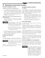
Prepare water heater
Figure 2-3
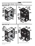
Installing Propane Orifice - Model 399
Model 399
1. Remove the top and front access covers from the unit (no
tools required for removal).
2. Remove the three screws securing the venturi to the
blower.
Note:
When separating the venturi from the blower, take
care not to damage the O-ring inside the blower
(FIG. 2-3).
3. Remove the four screws securing the gas valve to the
venturi (FIG. 2-3).
4. Locate the propane orifice disk from the conversion kit
bag. Verify that the stamping on the orifice disk matches
the water heater size (see Table 2A on page 13).
5. Remove the existing orifice from the O-ring in the side of
the gas valve and replace it with the orifice from the kit.
Position and secure the orifice in the valve as shown in
FIG. 2-3.
6. Reposition the gas valve against the venturi and replace
the screws (FIG. 2-3) securing the valve to the venturi.
7. Inspect the O-ring inside the blower. Handle the O-ring
with care, do not damage. Reposition the venturi against
the blower and replace the screws securing the venturi to
the blower (FIG. 2-3).
8. After installation is complete, attach the propane
conversion label (in the conversion kit bag) next to the
water heater rating plate. Attach the LP caution label (in
the conversion kit bag) to the left side of the unit in the
lower left corner.
9. Replace the top and front access covers.
DANGER
Armor 399: Inspect the O-ring when the
blower is disassembled. The O-ring must
be in good condition and must be
installed. Failure to comply will cause a
gas leak, resulting in severe personal injury
or death.
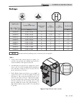
Figure 2-4
Gas Valve Adjustment - Model 500
Model 500
1. Remove the top access cover from the unit (no tools
required for removal).
2. Turn the adjustment screw on the gas valve clockwise
until it stops. Then turn the adjustment screw
counterclockwise four and three quarter (4 3/4) turns
(see FIG. 2-4).
3. Use a combustion analyzer to verify CO
2
is within the
range of 9.6 – 10.5%. If not, adjust the screw
counterclockwise
incrementally to raise CO
2
and
clockwise
to lower CO
2
(FIG. 2-4).
4. After adjustment is complete, attach the propane
conversion label (in the conversion kit bag) next to the
water heater rating plate. Attach the LP caution label (in
the conversion kit bag) to the left side of the unit in the
lower left corner.
5. Replace the top access cover.
WARNING
After converting to LP, check combustion
per the Start-up procedure in Section 10 of
this manual. Failure to check and verify
combustion could result in severe personal
injury, death, or substantial property
damage.
WARNING
After converting to LP, check combustion
per the Start-up procedure in Section 10
of this manual. Failure to check and
verify combustion could result in severe
personal injury, death, or substantial
property damage.
14
Содержание Armor AWL150PM
Страница 49: ...Installation Operation Manual 49 8 Field wiring continued Figure 8 3 Low Voltage Field Wiring Connections ...
Страница 53: ...Installation Operation Manual 53 Figure 10 2 Operating Instructions Models 150 285 10 Start up continued ...
Страница 54: ...Installation Operation Manual 54 10 Start up Figure 10 3 Operating Instructions Models 399 800 ...
Страница 71: ...Notes ...