


Operating Manual
Tangential Rolling System T18F - T27F
31
www.lmt-fette.com
■
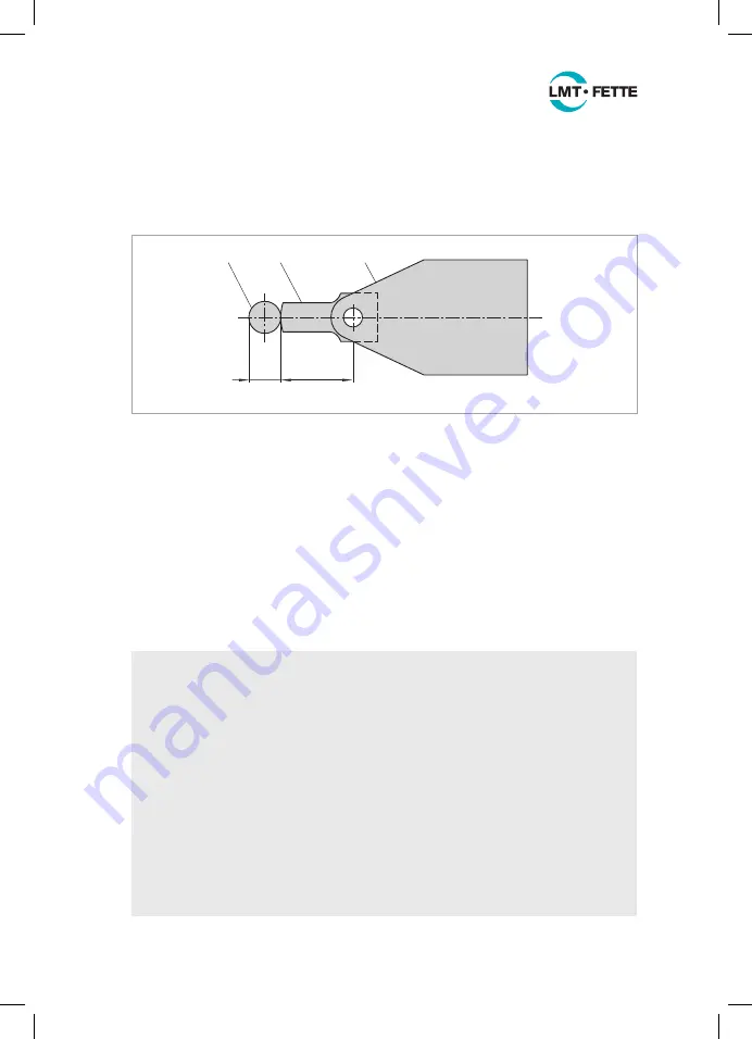
Move the rolling head holder with the setting gauge towards the workpiece (1)
until the leading edge of the setting gauge touches the initial diameter d
A
on the
workpiece. This position is the end point of the traverse path. The rolling head
must not be moved any further onto the workpiece. Especially in the case of
cam-controlled machines a fixed stop must be set here.
d
A
F
1
2
3
Figure 18: Using the setting gauge
3. It is an advantage when the tangential rolling head remains at position 3 depending
on the application for a few dwell-time rotations n
d
= 2 … 5. It is important here that
the maximum number of total workpiece rotations n
d
+ n
w
does not exceed < 35.
Especially in the case of cam-controlled machine tools it may be advisable not to
dwell at the position.
The dwell time t
d
is calculated as follows:
t
d
= 60 · n
d
______
n
[s]
4. Move the rolling head rapidly back to position 1. This completes the rolling process.
Instructions for designing a control cam for cam-controlled machine tools
A control cam for thread rolling should be produced by the machine manufacturer.
For this, the following data is required:
■
Machine manufacturer, machine type and serial no.
■
Spindle position (rolling station)
■
Thread size and material
■
Workpiece rotation during rolling
■
Spindle RPM
■
Path in working feed
The following should be noted when designing the control cam:
■
The cam roller should be kept as small as possible.
■
The return stroke must be ensured by a return cam or by a reverse device.
■
It is essential that the feed motion of the cross slide, after the highest point of the cam
has been reached, is limited by a fixed stop.
■
The calculated working feed must be correct.
■
The maximum number of n
W max
= 35 must not be exceeded.
LMT_Bedienungsanleitung_T18F_T27F_e.indd 31
02.08.11 17:40