background image

Gocator 2300 & 2880 Series

Gocator Web Interface • Scan Setup and Alignment • 117

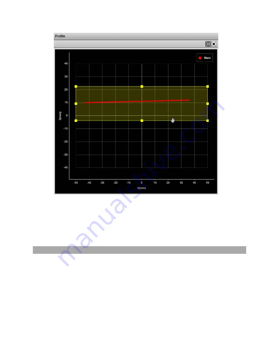
To set up a region of interest:

1.

Move the mouse cursor to the rectangle.

The rectangle is automatically displayed when a setup or measurement requires an area to be
specified.

2.

Drag the rectangle to move it, and use the handles on the rectangle's border to resize it.

Intensity Output

Gocator sensors can produce intensity images that measure the amount of light reflected by an object.
An 8-bit intensity value is output for each range value along the laser line . Gocator applies the same
coordinate system and resampling logic as the ranges to the intensity values.

Intensity output is enabled by checking the

Acquire Intensity

checkbox in the

Scan Mode

panel.

Содержание Gocator 2300 Series

Страница 1: ...USER MANUAL Gocator 2300 2880 Series Firmware version 4 3 x xx Document revision D ...

Страница 2: ... machine readable form without prior written consent of LMI Technologies Inc Trademarks and Restrictions Gocator is a registered trademark of LMI Technologies Inc Any other company or product names mentioned herein may be trademarks of their respective owners Information contained within this manual is subject to change This product is designated for use solely as a component and as such it does n...

Страница 3: ...eration 33 Network Setup 34 Client Setup 34 Gocator Setup 36 Running a Standalone Sensor System 36 Running a Dual Sensor System 37 Next Steps 40 Theory of Operation 42 3D Acquisition 42 Principle of 3D Acquisition 42 Resolution and Accuracy 43 X Resolution 43 Z Resolution 43 Z Linearity 44 Profile Output 45 Coordinate Systems 45 Sensor Coordinates 45 System Coordinates 45 Uniform Spacing Data Resa...

Страница 4: ... 110 Profile Mode 111 Surface Mode 113 Height Map Color Scale 115 Region Definition 116 Intensity Output 117 Models and Part Matching 118 Model Page Overview 118 Part Matching 119 Using Edge Detection 120 Creating a Model 123 Modifying a Model s Edge Points 125 Adjusting Target Sensitivity 128 Setting the Match Acceptance Criteria 129 Running Part Matching 129 Using Bounding Box and Ellipse 129 Co...

Страница 5: ...g the Emulator 224 Adding a Scenario to the Emulator 225 Running a Scenario 226 Removing a Scenario from the Emulator 227 Using Replay Protection 227 Stopping and Restarting the Emulator 228 Working with Jobs and Data 228 Creating Saving and Loading Jobs 228 Playback and Measurement Simulation 229 Downloading Uploading and Exporting Replay Data 230 Downloading and Uploading Jobs 232 Scan Model and...

Страница 6: ...ilePosition 267 ProfileStrip 268 Script 270 SurfaceBoundingBox 270 SurfaceCsHole 272 SurfaceEllipse 274 SurfaceHole 275 SurfaceOpening 277 SurfacePlane 279 SurfacePosition 280 SurfaceStud 281 SurfaceVolume 283 Output 284 Ethernet 284 Ascii 286 EIP 287 Modbus 287 Digital0 and Digital1 287 Analog 288 Serial 289 Selcom 289 Ascii 290 Transform 290 Device 291 Part Models 292 Edge Points 292 Configurati...

Страница 7: ...tect Edges 324 Add Tool 324 Add Measurement 324 Read File Progressive 325 Export CSV Progressive 326 Export Bitmap Progressive 327 Upgrade Commands 327 Start Upgrade 328 Start Upgrade Extended 328 Get Upgrade Status 329 Get Upgrade Log 329 Results 329 Data Results 330 Stamp 330 Video 331 Profile 332 Resampled Profile 333 Profile Intensity 333 Surface 334 Surface Intensity 334 Measurement 335 Align...

Страница 8: ...t Types 367 GoDataSet Type 368 Measurement Values and Decisions 368 Operation Workflow 369 Initialize GoSdk API Object 369 Discover Sensors 370 Connect Sensors 370 Configure Sensors 370 Enable Data Channels 370 Perform Operations 370 Limiting Flash Memory Write Operations 372 Tools and Native Drivers 373 Sensor Recovery Tool 373 GenTL Driver 375 16 bit RGB Image 376 16 bit Grey Scale Image 377 Reg...

Страница 9: ...0 800 415 Master 400 800 Electrical Specifications 416 Master 400 800 Dimensions 417 Master 1200 2400 418 Master 1200 2400 Electrical Specifications 419 Master 1200 2400 Dimensions 420 Accessories 421 Return Policy 423 Software Licenses 424 Support 430 Contact 431 ...

Страница 10: ...devices This documentation describes how to connect configure and use a Gocator It also contains reference information on the device s protocols and job files B series Gocator sensors are only supported by firmware version 4 3 or later Notational Conventions This guide uses the following notational conventions Follow these safety guidelines to avoid potential injury or property damage Consider thi...

Страница 11: ...y items that the customer may be required to provide in their own equipment e g remote interlocks key control refer to the references below for detailed information As such these sensors do not fully comply with the standards relating to laser products specified in IEC 60825 1 and FDA CFR Title 21 Part 1040 Use of controls or adjustments or performance of procedures other than those specified here...

Страница 12: ...t to 1 mW entering an aperture of 7 mm diameter the assumed size of the pupil Class 3R laser components Class 3R laser products emit radiation where direct intrabeam viewing is potentially hazardous but the risk is lower with 3R lasers than for 3B lasers Fewer manufacturing requirements and control measures for 3R laser users apply than for 3B lasers Class 3B laser components Class 3B components a...

Страница 13: ...ss 3B Responsibilities LMI Technologies has filed reports with the FDA to assist customers in achieving certification of laser products These reports can be referenced by an accession number provided upon request Detailed descriptions of the safety items that must be added to the system design are listed below Remote Interlock A remote interlock connection must be present in Class 3B laser systems...

Страница 14: ...ng sign example IEC warning sign example Nominal Ocular Hazard Distance NOHD Nominal Ocular Hazard Distance NOHD is the distance from the source at which the intensity or the energy per surface unit becomes lower than the Maximum Permissible Exposure MPE on the cornea and on the skin The laser beam is considered dangerous if the operator is closer to the source than the NOHD The following table sh...

Страница 15: ... use the following formula NOHD Model Constant MPE Model Constant includes a consideration of the fan angle for the individual models Systems Sold or Used in the USA Systems that incorporate laser components or laser products manufactured by LMI Technologies require certification by the FDA Customers are responsible for achieving and maintaining this certification Customers are advised to obtain t...

Страница 16: ...devices Wires connecting to the sensor should not be handled while the sensor is powered Doing so may cause electrical shock to the user or damage to the equipment Environment and Lighting Avoid strong ambient light sources The imager used in this product is highly sensitive to ambient light hence stray light may have adverse effects on measurement Do not operate this device near windows or lighti...

Страница 17: ...instruments To ensure the highest accuracy is achieved in all measurements the windows on the front of the sensor should be kept clean and clear of debris Use care when cleaning sensor windows Use dry clean air to remove dust or other dirt particles If dirt remains clean the windows carefully with a soft lint free cloth and non streaking glass cleaner or isopropyl alcohol Ensure that no residue is...

Страница 18: ...ndalone systems are typically used when only a single Gocator sensor is required The sensor can be connected to a computer s Ethernet port for setup and can also be connected to devices such as encoders photocells or PLCs Dual Sensor System In a dual sensor system two Gocator sensors work together to perform profiling and output the combined results The controlling sensor is referred to as the Mai...

Страница 19: ... to connect two or more sensors into a multi sensor system Gocator Master cordsets are used to connect the sensors to a Master The Master provides a single point of connection for power safety encoder and digital inputs A Master 400 800 1200 2400 can be used to ensure that the scan timing is precisely synchronized across sensors Sensors and client computers communicate via an Ethernet switch 1 Gig...

Страница 20: ...Gocator 2300 2880 Series Getting Started System Overview 20 ...

Страница 21: ... blue Range Indicator Illuminates when camera detects laser light and is within the target range green Laser Indicator Illuminates when laser safety input is active amber Serial Number Unique sensor serial number Gocator 2300 2880 Cordsets Gocator 2300 and 2880 sensors use two types of cordsets The Power Ethernet cordset provides power laser safety interlock to the sensor It is also used for senso...

Страница 22: ...thernet Port Connects to the RJ45 connector labeled Ethernet on the Power LAN to Master cordset Master Power Port Connects to the RJ45 connector labeled Power Sync on the Power LAN to Master cordset Provides power and laser safety to the Gocator Sensor I O Port Connects to the Gocator I O cordset Master Host Port Connects to the host PC s Ethernet port Power Accepts power 48 V Power Switch Toggles...

Страница 23: ...ors Item Description Sensor Ports Master connection for Gocator sensors no specific order required Ground Connection Earth ground connection point Laser Safety Laser safety connection Encoder Accepts encoder signal Input Accepts digital input See Master 400 800 on page 415 for pinout details Master 1200 2400 The Master 1200 and the Master 2400 allow you to connect more than two sensors The Master ...

Страница 24: ... details Calibration Targets Targets are used for alignment and calibrating encoder systems Disks are typically used with systems containing a single sensor and can be ordered from LMI Technologies When choosing a disk for your application select the largest disk that fits entirely within the required field of view See Accessories on page 421 for disk part numbers For wide multi sensor systems bar...

Страница 25: ...Gocator 2300 2880 Series Getting Started Hardware Overview 25 See Aligning Sensors on page 94 for more information on alignment ...

Страница 26: ...sure electrical continuity between the mounting frame and the Gocator s connectors The frame or electrical cabinet that the Gocator is mounted to must be connected to earth ground Recommended Grounding Practices Cordsets If you need to minimize interference with other equipment you can ground the Power Ethernet or the Power Ethernet to Master cordset depending on which cordset you are using by ter...

Страница 27: ...must be connected to earth ground Mounting Sensors should be mounted using four or six depending on the model M5 x 0 8 pitch screws of suitable length The recommended thread engagement into the housing is 8 10 mm Proper care should be taken in order to ensure that the internal threads are not damaged from cross threading or improper insertion of screws With the exception of Gocator 2880 sensors sh...

Страница 28: ... sensors are high accuracy devices The temperature of all of its components must be in equilibrium When the sensor is powered up a warm up time of at least one hour is required to reach a consistent spread of temperature within the sensor Orientations The examples below illustrate the possible mounting orientations for standalone and dual sensor systems See Dual Sensor System Layout on page 58 for...

Страница 29: ...eries Getting Started Installation 29 Single sensor on robot arm Dual Sensor System Orientations Side by side for wide area measurement Wide Main must be on the left side when looking into the connector of the Buddy Wide ...

Страница 30: ...Gocator 2300 2880 Series Getting Started Installation 30 Above below for two sided measurement Opposite Main must be on the top with Buddy on the bottom Opposite ...

Страница 31: ...d in parallel The diagram above shows the clearance distance and measurement range required in a typical setup Use the specification estimator Gocator 2375_Specification_Estimator xlsx to calculate the X and Z resolution of the sensors with different combinations of clearance distance and measurement range System Setup A typical Gocator 2375 system is set up as a multi sensor system The sensors ar...

Страница 32: ...pped with a default IP address of 192 168 1 10 Before you add a sensor to a multi sensor system its firmware version must match that of the other sensors and its IP address must be unique To configure a Gocator 2375 for the first time 1 Set up the sensor s IP address a Follow the steps in Running a Standalone Sensor System on page 36 b Make sure that there is no other sensor in the network with th...

Страница 33: ...w to operate a multi sensor system using the SDK APPNOTE_Gocator_4 x_Multi_Sensor_Guide zip Explains how to use the SDK to create a multi sensor system and multiplex their timing Gocator 2000 2300_appnote_multi sensor alignment calibration zip Explains how to use the SDK to perform alignment calibration of a multi sensor system Example code is included with both of the application notes above ...

Страница 34: ... are configured to 192 168 1 10 as the default IP address For a dual sensor system the Main and Buddy sensors must be assigned unique addresses before they can be used on the same network Before proceeding connect the Main and Buddy sensors one at a time to avoid an address conflict and use the steps in See Running a Dual Sensor System on page 37 to assign each sensor a unique address To connect t...

Страница 35: ...nternet Protocol Version 4 TCP IPv4 and then click Properties d Select the Use the following IP address option e Enter IP Address 192 168 1 5 and Subnet Mask 255 255 255 0 then click OK Mac OS X v10 6 a Open the Network pane in System Preferences and select Ethernet b Set Configure to Manually c Enter IP Address 192 168 1 5 and Subnet Mask 255 255 255 0 then click Apply See Troubleshooting on page...

Страница 36: ...r The power indicator blue should turn on immediately 2 Enter the sensor s IP address 192 168 1 10 in a web browser 3 Log in as Administrator with no password The interface display language can be changed using the language option After selecting the language the browser will refresh and the web interface will display in the selected language 4 Go to the Manage page 5 Ensure that Replay mode is of...

Страница 37: ...ubleshooting on page 382 10 Press the Stop button The laser should turn off Running a Dual Sensor System All sensors are shipped with a default IP address of 192 168 1 10 Ethernet networks require a unique IP address for each device so you must set up a unique address for each sensor To configure a dual sensor system 1 Turn off the sensors and unplug the Ethernet network connection of the Main sen...

Страница 38: ...age 6 Modify the IP address to 192 168 1 11 in the Networking category and click the Save button When you click the Save button you will be prompted to confirm your selection 7 Turn off the sensors re connect the Main sensor s Ethernet connection and power cycle the sensors After changing network configuration the sensors must be reset or power cycled before the change will take effect 8 Enter the...

Страница 39: ...er of the Buddy sensor is listed in the Available Sensors panel 12 Select the Buddy sensor and click the Assign button The Buddy sensor will be assigned to the Main sensor and its status will be updated in the System panel The firmware on Main and Buddy sensors must be the same for Buddy assignment to be successful If the firmware is different connect the Main and Buddy sensor one at a time and fo...

Страница 40: ... you used the Start button to start the sensors The laser should turn off Next Steps After you complete the steps in this section the Gocator measurement system is ready to be configured for an application using the software interface The interface is explained in the following sections System Management and Maintenance page 56 Contains settings for sensor system layout network motion and alignmen...

Страница 41: ...Gocator 2300 2880 Series 41 Toolbar page 48 Controls sensor operation manages jobs and replays recorded measurement data ...

Страница 42: ...ction of the light off the target Because of this triangulation angle the laser line appears in different positions on the camera depending on the 3D shape of the target Gocator sensors are always pre calibrated to deliver 3D data in engineering units throughout the specified measurement range Target objects are typically moved under the sensor on a transportation mechanism such as a conveyor belt...

Страница 43: ...X resolution X resolution is important for how accuratel the width of a target can be measured NOTE When the Gocator runs in Profile mode and Uniform Spacing is enabled the 3D data is resampled to an X interval that is different from the raw camera resolution Z Resolution Z resolution is the variability of the height measurement in each individual 3D point with the target at a fixed position This ...

Страница 44: ...ence between the actual distance to the target and the measured distance to the target throughout the measurement range Z Linearity is expressed in the Gocator data sheet as a percentage of the total measurement range Z Linearity gives an indication of the sensor s ability to measure absolute distance ...

Страница 45: ...e MR and FOV In Surface data the Y axis represents the relative position of the part in the direction of travel Y position increases as the object moves forward increasing encoder position System Coordinates Alignment is used with a single sensor to compensate for mounting misalignment and to set a zero reference such as a conveyor belt surface Alignment is also used to set a common coordinate sys...

Страница 46: ... spacing interval can be set under the Spacing tab in the Sensor panel on Scan page As a result when uniform spacing is enabled in the Ethernet data channel only the range values Z are reported and the X positions can be reconstructed through the array index at the receiving end the client Resampling to uniform spacing reduces the complexity for downstream algorithms to process the profile data fr...

Страница 47: ...lustrated below Element Description 1 Manage page Contains settings for sensor system layout network motion and alignment handling jobs and sensor maintenance See System Management and Maintenance on page 56 2 Scan page Contains settings for scan mode trigger source detailed sensor configuration and performing alignment See Scan Setup and Alignment on page 73 3 Model page Lets you set up part matc...

Страница 48: ...e and on page 134 for its use when the Measure page is active 11 Log Displays messages from the sensor errors warnings and other information See Log on page 54 Toolbar The toolbar is used for performing operations such as managing jobs working with replay data and starting and stopping the sensor Element Description 1 Job controls For saving and loading jobs 2 Replay data controls For downloading ...

Страница 49: ...t Alignment Alignment can either be fixed or dynamic as controlled by the Alignment Reference setting in Motion and Alignment in the Manage page Alignment is saved automatically at the end of the alignment procedure when Alignment Reference is set to Fixed When Alignment Reference is set to Dynamic however you must manually save the job to save alignment Network Address Network address changes are...

Страница 50: ...roubleshooting and fine tuning measurements but can also be helpful during setup Recording and playback are controlled by using the toolbar controls Recording and playback controls when replay is off To record live data 1 Toggle Replay mode off by setting the slider to the left in the Toolbar 2 Press the Record button to enable recording When recording is enabled and replay is off the sensor will ...

Страница 51: ...play frame To simulate measurements on replay data 1 Toggle Replay mode on by setting the slider to the right in the Toolbar The slider s background turns blue and a Replay Mode Enabled message is displayed To change the mode Replay Protection must be unchecked 2 Go to the Measure page Modify settings for existing measurements add new measurement tools or delete measurement tools as desired For in...

Страница 52: ...ata using third party tools You can only upload replay data to the same sensor model that was used to create the data Replay data is not loaded or saved when you load or save jobs To download replay data l Click the Download button To upload replay data 1 Click the Upload button If you have unsaved changes in the current job the firmware asks whether you want to discard the changes Do one of the f...

Страница 53: ...t 1 Click the Export button and select Export Range Data as CSV In Profile mode all data in the record buffer is exported In Surface mode only data at the current replay location is exported Use the playback control buttons to move to a different replay location for information on playback see To replay data in Recording Playback and Measurement Simulation on page 50 2 Optionally convert exported ...

Страница 54: ...eed current frame rate The CPU bar in the Metrics panel at the top of the interface displays how much of the CPU is being utilized A warning symbol will appear next to the CPU bar if the sensor drops profiles because the CPU is over loaded CPU at 100 CPU warning message The Speed bar displays the frame rate of the sensor A warning symbol will appear next to it if triggers external input or encoder...

Страница 55: ...nd can be used to adjust regions of interest Depending on the selected operation mode page 74 the data viewer can display video images 3D profiles or 3D surfaces For details see Data Viewer on page 107 When the Measure page is active the data viewer displays sensor data onto which representations of measurement tools and their measurements are superimposed For details see Data Viewer on page 134 B...

Страница 56: ... Sensor System Contains settings for configuring sensor system and layout and boot up See Sensor System on the next page 2 Networking Contains settings for configuring the network See Networking on page 61 3 Motion and Alignment Contains settings to configure the encoder See Motion and Alignment on page 62 4 Jobs Lets you manage jobs stored on the sensor See Jobs on page 64 5 Security Lets you cha...

Страница 57: ...ut standalone or dual sensor systems and provides other system settings Dual sensor layouts are only displayed when a Buddy sensor has been assigned Sensor Autostart With the Autostart setting enabled laser ranging profiling and measurement functions will begin automatically when the sensor is powered on Autostart must be enabled if the sensor will be used without being connected to a computer To ...

Страница 58: ...dinates Orientation Example Standalone The sensor operates as an isolated device Reverse The sensor operates as an isolated device but in a reverse orientation Wide Sensors are mounted in Left Main and Right Buddy positions for a larger combined field of view Sensors may be angled to avoid occlusions Reverse Sensors are mounted in a left right layout as with the Wide layout but the Buddy sensor is...

Страница 59: ...clicking on one of the layout buttons See the table above for information on layouts Buddy Assignment In a dual sensor system the Main sensor assumes control of the Buddy sensor after the Buddy sensor is assigned to the Main sensor Configuration for both sensors can be performed through the Main sensor s interface Main and Buddy sensors must be assigned unique IP addresses before they can be used ...

Страница 60: ...t if a sensor cannot be assigned as a Buddy The Buddy sensor will be assigned to the Main sensor and its status will be updated in the System panel To remove a Buddy click on the Remove button Exposure Multiplexing If the Main and Buddy sensors are mounted such that the camera from one sensor can detect the laser from the other sensor the Exposure Multiplexing option can be used to eliminate laser...

Страница 61: ... laser if the temperature exceeds the safe operating range You can override the setting by disabling the overheat protection Disabling the setting is not recommended Disabling the overheat protection feature could lead to premature laser failure if the sensor operates outside the specified temperature range To enable disable overheat temperature protection 1 Check uncheck the Over Temperature Prot...

Страница 62: ...ategory specify the Type IP Subnet Mask and Gateway settings The Gocator sensor can be configured to use DHCP or assigned a static IP address 3 Click on the Save button You will be prompted to confirm your selection Motion and Alignment The Motion and Alignment category on the Manage page lets you configure alignment reference encoder resolution and travel speed ...

Страница 63: ...typically used when the sensor s position relative to the object scanned is always changing for example when the sensor is mounted on a robot arm moving to different scanning locations To configure alignment reference 1 Go to the Manage page and click on the Motion and Alignment category 2 In the Alignment section choose Fixed or Dynamic in the Alignment Reference drop down Encoder Resolution You ...

Страница 64: ...er is correctly wired to the Gocator and to manually calibrate encoder resolution that is by moving the conveyor system a known distance and making a note of the encoder value at the start and end of movement Travel Speed The Travel Speed setting is used to correctly scale scans in the direction of travel in systems that lack an encoder but have a conveyor system that is controlled to move at cons...

Страница 65: ...saved changes Delete button Deletes the job that is selected in the job list Set as Default button Sets the selected job as the default to be loaded when the sensor starts When the default job is selected this button is used to clear the default Download button Downloads the selected job to the client computer Upload button Uploads a job from the client computer Jobs can be loaded currently activa...

Страница 66: ...o the Manage page and click on the Jobs category 2 Select a job in the Jobs list 3 Click on the appropriate button for the operation Security Gocator sensors can be secured with passwords to prevent unauthorized access Each sensor has two accounts Administrator and Technician Gocator Account Types Account Description Administrator The Administrator account has privileges to use the toolbar loading...

Страница 67: ...or change the password for the Technician account 1 Go to the Manage page and click on the Security category 2 In the Technician section enter the Technician account password and password confirmation 3 Click Change Password The new password will be required the next time that a technician logs in to the sensor If the administrator or technician password is misplaced the sensor can be recovered us...

Страница 68: ...a sensor including jobs and alignment An Administrator should create a backup file in the unlikely event that a sensor fails and a replacement sensor is needed If this happens the new sensor can be restored with the backup file To create a backup 1 Go to the Manage page and click on the Maintenance category 2 Click the Backup button under Backup and Restore 3 When you are prompted save the backup ...

Страница 69: ...r making a backup Before proceeding you should perform a backup Restoring to factory defaults cannot be undone 3 Click the Factory Restore button under Factory Restore You will be prompted whether you want to proceed Firmware Upgrade LMI recommends routinely updating firmware to ensure that Gocator sensors always have the latest features and fixes In order for the Main and Buddy sensors to work to...

Страница 70: ...ww lmi3D com support downloads To upgrade the firmware 1 Go to the Manage page and click on the Maintenance category 2 Click the Upgrade button in the Firmware section 3 Provide the location of the firmware file in the File dialog 4 Wait for the upgrade to complete After the firmware upgrade is complete the sensor will self reset If a buddy has been assigned it will be upgraded and reset automatic...

Страница 71: ...t file in the emulator the filename you provide here is displayed in the emulator s scenario list Support files end with the gs extension but you do not need to type the extension in Filename 3 Optional In Description type a description of the support file When you create a scenario from a support file in the emulator the description is displayed below the emulator s scenario list 4 Click Download...

Страница 72: ... download the Gocator SDK from within the Web interface To download the SDK 1 Go to the Manage page and click on the Support category 2 Next to Software Development Kit SDK click Download 3 Choose the location for the SDK on the client computer For more information on the SDK see Software Development Kit on page 364 ...

Страница 73: ...o Profile or Surface and other options See Scan Modes on the next page 2 Trigger panel Contains trigger source and trigger related settings See Triggers on page 75 3 Sensor panel Contains settings for an individual sensor such as active area or exposure See Sensor on page 80 4 Alignment panel Used to perform alignment See Alignment on page 92 5 Filters panel Contains settings for post processing o...

Страница 74: ... 80 Exposure page 84 Job Files page 236 Specify mounting orientations for dual sensor systems Dual Sensor System Layout page 58 Calibrate the system so that laser profile data can be aligned to a common reference and values can be correctly scaled in the axis of motion Aligning Sensors page 94 Set up the part detection logic to create discrete objects from surfaces or profiles Part Detection page ...

Страница 75: ...s not available Acquire Intensity When this option is enabled an intensity value will be produced for each laser profile point Triggers A trigger is an event that causes a sensor to take a single picture Triggers are configured in the Trigger panel on the Scan page When a trigger is processed the laser is strobed and the camera exposes to produce an image The resulting image is processed inside th...

Страница 76: ...ption Ignore Backward A scan is triggered only when the target object moves forward If the target object moves backward it must move forward by at least the distance of one encoder spacing to trigger the next scan Bi directional A scan is triggered when the target object moves forward or backward ...

Страница 77: ...quency higher than the maximum frame rate some triggers may not be accepted The Trigger Drops Indicator in the Dashboard page can be used to check for this condition See Digital Inputs on page 410 for more information on connecting external input to Gocator sensors Software A network command can be used to send a software trigger See Protocols on page 294 for more information For examples of typic...

Страница 78: ...an be used to produce a snapshot for profile measurement For example a photocell can be connected as an external input to generate a trigger pulse when a target object has moved into position An external input can also be used to gate the trigger signals when time or encoder triggering is used For example a photocell could generate a series of trigger pulses as long as there is a target in positio...

Страница 79: ...only when the external input is asserted This setting is not displayed when Surface Generation is set to Fixed Length Variable Length or Rotational see on page 100 See See Digital Inputs on page 410 for more information on connecting external input to Gocator sensors Behavior Encoder Specifies how the Gocator sensor is triggered when the target moves Can be Track Backward Ignore Backward or Bi Dir...

Страница 80: ...e panel header 3 Select the trigger source from the drop down 4 Configure the settings See the trigger parameters above for more information 5 Save the job in the Toolbar by clicking the Save button Sensor The following sections describe the settings that are configured in the Sensor panel on the Scan page Active Area Active area refers to the region within the sensor s maximum field of view that ...

Страница 81: ...rea is specified separately for each sensor 5 Click on the Active Area tab 6 Click the Select button 7 Click the Acquire button to see a scan while setting the active area 8 Set the active area Enter the active area values in the edit boxes or adjust the active area graphically in the data viewer 9 Click the Save button in the Sensor panel Click the Cancel button to cancel setting the active area ...

Страница 82: ...is typically used in road or web scanning applications where the target is a continuous flat surface A laser line remains tracked as long as the percentage of detected laser points exceeds the user defined search threshold When the sensor loses track of the laser line the sensor will search for the laser line using the full active area To enable the tracking window 1 Go to the Scan page 2 Choose P...

Страница 83: ...ng the Save button The sensor adjusts the position of the tracking window so that the area is centered around the average height of the entire visible laser profile You should adjust the lighting and the active area to remove all background objects such as the conveyor belt surface ambient lights etc Transformations The transformation settings are used to control how profiles are converted from se...

Страница 84: ...an be helpful to detect laser signals on dark or distant surfaces but increasing exposure time decreases the maximum speed Different target surfaces may require different exposures for optimal results Gocator sensors provide three exposure modes for the flexibility needed to scan different types of target surfaces Exposure Mode Description Single Uses a single exposure for all objects Used when th...

Страница 85: ...le exposure is used when the target surface is uniform and is the same for all parts To enable single exposure 1 Place a representative target in view of the sensor The target surface should be similar to the material that will normally be measured 2 Go to the Scan page 3 Expand the Sensor panel by clicking on the panel header 4 Click the button corresponding to the sensor you want to configure Th...

Страница 86: ... adjust the exposure to yield the best profile This is used when the target surface changes from scan to scan To enable dynamic exposure 1 Go to the Scan page 2 Expand the Sensor panel by clicking on the panel header or the button 3 Click the button corresponding to the sensor you want to configure The button is labeled Top Bottom Top Left or Top Right depending on the system Exposure can be confi...

Страница 87: ...h set to a different exposure level For each exposure the sensor will perform a complete scan at the current frame rate making the effective frame rate slower For example if two exposures are selected then the speed will be half of the single exposure frame rate The sensor will perform a complete multi exposure scan for each external input or encoder trigger The resulting profile is a composite cr...

Страница 88: ...d to capture the intensity output 9 Run the sensor and check that laser profiling is satisfactory If laser profiling is not satisfactory adjust the exposure values manually Switch to Video mode to use video to help tune the exposure see Exposure on page 84 for details Spacing The Spacing tab lets you configure settings related to spacing sub sampling and spacing interval Sub Sampling Sub sampling ...

Страница 89: ...g value 6 Save the job in the Toolbar by clicking the Save button 7 Check that laser profiling is satisfactory Spacing Interval Spacing interval is the spacing between data points in resampled data In Profile mode resampled data is only produced if the Uniform Spacing option in the Scan Mode panel is checked A larger interval creates profiles with lower X resolution reduces CPU usage and potential...

Страница 90: ...g interval This setting balances CPU load data output rate and X resolution Resolution Uses the highest X resolution within the active area as the spacing interval This setting maximizes resolution but has higher CPU load and has the highest data output rate i e greatest detail l Choose Custom and move the slider to a precise value 7 Save the job in the Toolbar by clicking the Save button Material...

Страница 91: ...e laser itself A lower Spot Width Max setting reduces the chance of false detection but limits the ability to detect features surfaces that elongate the spot Spot Selection Determines the spot selection method Best selects the strongest spot in a given column on the imager Top selects the topmost spot or the one farthest to the left on the imager and Bottom selects the bottommost spot or the one f...

Страница 92: ...or Top Right depending on the system Materials can be configured separately for each sensor 4 Click on the Materials tab 5 Choose a material in the Materials drop down or choose Custom to manually configure settings See the table above for the customizable settings 6 Save the job in the Toolbar by clicking the Save button 7 Check that laser profiling is satisfactory After adjusting the setting con...

Страница 93: ...ed is always changing e g when the sensor is mounted on a robot arm moving to different scanning locations Alignment With and Without Encoder Calibration For systems that use an encoder encoder calibration can be performed while aligning sensors The table below summarizes the differences between performing alignment with and without encoder calibration calibration With encoder calibration Without ...

Страница 94: ...l by clicking on the panel header or the button 5 Ensure that all sensors have a clear view of the target surface Remove any irregular objects from the sensor s field of view that might interfere with alignment If using a bar for a dual sensor system ensure that the lasers illuminate a reference hole on the bar To perform alignment for stationary targets 1 In the Alignment panel select Stationary ...

Страница 95: ...gin for the system Z axis To perform alignment for moving targets 1 Do one of the following if you have not already done so l If the system uses an encoder configure encoder resolution See Encoder Resolution on page 63 for more information l If the system does not use an encoder configure travel speed See Travel Speed on page 64 for more information 2 In the Alignment panel select Moving as the Ty...

Страница 96: ... current exposure mode 8 Engage the transport system When the calibration target has passed completely through the laser plane the calibration process will complete automatically To properly calibrate the travel speed the transport system must be running at the production operating speed before the target passes through the laser plane 9 Use Profile mode to inspect alignment results Laser profiles...

Страница 97: ... reflectivity for example dark or specular surface areas or to actual gaps in the surface Median Substitutes the value of a data point with the median within a specified window around the data point Smoothing Applies moving window averaging to reduce random noise Decimation Reduces the number of data points Filters are applied in the order displayed in the table above The filters are configured in...

Страница 98: ...ect the maximum width value The value represents the maximum gap width that the Gocator will fill Gaps wider than the maximum width will not be filled 6 Save the job in the Toolbar by clicking the Save button 7 Check that the laser profiling is satisfactory Median The Median filter substitutes the value of a data point with the median calculated within a specified window around the data point Miss...

Страница 99: ...othing works by calculating a moving average across samples within the same profile Y smoothing works by calculating a moving average in the direction of travel at each X location If both X and Y smoothing are enabled the data is smoothed along X axis first then along the Y axis Missing data points will not be filled with the mean value calculated from data points in the neighbourhood To configure...

Страница 100: ...lected you will not be able to configure the decimation filter 3 Expand the Filters panel by clicking on the panel header or the button 4 Click on the Decimation tab 5 Enable the X or Y setting and select the decimation window value 6 Save the job in the Toolbar by clicking the Save button 7 Check that the laser profiling is satisfactory Surface Generation The sensor can generate a surface by comb...

Страница 101: ...s of a fixed length in mm using the value in the Length setting For correct length measurement you should ensure that motion is calibrated that is encoder resolution for encoder triggers or travel speed time triggers The Type setting provides two types of start triggers o Sequential Continuously generates back to back fixed length surfaces o External Input A pulse on the digital input triggers the...

Страница 102: ...al input to a Gocator sensor see on page 410 You can optionally enable part detection to process the profilesurface after it has been generated but the generation itself does not depend on the detection logic To do this check Enabled in the Part Detection panel Rotational The sensor reorders profiles within a surface to be aligned with the encoder s index pulse That is regardless of the radial pos...

Страница 103: ...itional settings See the types and their settings described above Part Detection In Surface mode the Gocator sensor can analyze the 3D point cloud created from profiles to identify discrete objects Surface measurements can then be performed on each discrete object Part detection is configured using the Part Detection panel on the Scan page Part detection must be manually enabled when Type is set t...

Страница 104: ... a conveyor In an Opposite layout the threshold is applied to the difference between the top and the bottom profile A target thinner than the threshold value is ignored including places where only one of either top or bottom is detected To separate parts by gated external input set the Height Threshold to the active area Z offset i e minimum Z position of the current active area set Source to Time...

Страница 105: ...nsor s frame of reference is used The way the sensor s frame of reference is defined changes depending on the surface generation Type setting see on page 100 for more information l When parts are segmented from a continuous surface the surface generation Type setting is set to Continuous measurement values are relative to a Y origin at the center of the part the same as for Part frame of reference...

Страница 106: ...enabled 4 Adjust the settings See the part detection parameters above for more information Edge Filtering Part scans sometimes contain noise around the edges of the target This noise is usually caused by the sensor s light being reflected off almost vertical sides rounded corners etc Edge filtering helps reduce edge noise in order to produce more accurate and repeatable volume and area measurement...

Страница 107: ...set to Fixed Length Variable Length or Rotational Part detection is automatically enabled when Type is set to Continuous 3 Check the Edge Filtering checkbox to enable edge filtering 4 Configure the Width and Length settings The Width and Length settings represent the size of the filter on the X axis and the Y axis respectively 5 Set the Preserve Interior Feature setting if necessary The Preserve I...

Страница 108: ...ed Exposure View Exposure can be set to Single Dynamic or Multiple Different exposures can be displayed in the data viewer if more than one exposure has been set For details on setting exposure in the Exposure tab in the Sensor panel see on page 84 If the Multiple option is selected in the Exposure tab and multiple exposures have been set a drop down is displayed at the top of the data viewer This...

Страница 109: ...r Select Main or Buddy from the first drop down list next to View at the top of the data viewer 3 Select the exposure Select the exposure from the second drop down list next to View at the top of the data viewer This drop down is only be visible if the Multiple option has been selected To display a color exposure overlay on the video image to help set the correct exposure check Exposure Indication...

Страница 110: ...er line Spots and Dropouts Various settings can affect how the Material settings behave Video mode can be used to examine how the Material settings are affected To do this check the Show Spots option at the top of the data viewer to overlay spot data in the data viewer To show data dropouts check the Show Dropouts option at the top of the data viewer In the image below the white and gray squares r...

Страница 111: ... Gocator Web Interface Scan Setup and Alignment 111 See Material on page 90 for more information on settings for different materials Profile Mode When the Gocator is in Profile scan mode the data viewer displays profile plots ...

Страница 112: ...cally sets the display to the most appropriate display view To manually select the display view in the Scan page 1 Go to the Scan page 2 Choose Profile mode in the Scan Mode panel 3 Select the view The view from an individual sensor or the combined view of two sensors can be selected from the drop down list at the top of the data viewer Top View from a single sensor from the top sensor in an oppos...

Страница 113: ...e data to display from the View drop down Clicking on the 3D button displays Surface data in the 3D viewer The 3D model is overlaid with the information that corresponds to the selected View option View Option Information Profile Plots the last collected profile Only available in 2D view Surface Heightmap In 2D view displays the pseudo color height map In 3D view overlays the 2D pseudo color heigh...

Страница 114: ...Gocator 2300 2880 Series Gocator Web Interface Scan Setup and Alignment 114 2D viewer with height map overlay 2D viewer with grayscale overlay 2D viewer with intensity overlay ...

Страница 115: ...the Scan page selecting a panel e g Sensor or Part Detection panel will automatically set the display to the most appropriate display type and display view To manually select the display type and the display view in the Scan page 1 Go to the Scan page 2 Select the View options in the data viewer Profile Heightmap Grayscale Uniform or Intensity can be selected from the left drop down list The view ...

Страница 116: ...down and adjust the yellow region box in the data viewer to the desired location and size l To manually set the scale choose the Manual in the Range drop down and enter the minimum and maximum height to which the colors will be mapped Region Definition Regions such as an active area or a measurement region can be graphically set up using the data viewer When the Scan page is active the data viewer...

Страница 117: ...angle to move it and use the handles on the rectangle s border to resize it Intensity Output Gocator sensors can produce intensity images that measure the amount of light reflected by an object An 8 bit intensity value is output for each range value along the laser line Gocator applies the same coordinate system and resampling logic as the ranges to the intensity values Intensity output is enabled...

Страница 118: ...Web Interface Models and Part Matching 118 Models and Part Matching The following sections describe how to set up part matching using a model a bounding box or an ellipse Model Page Overview The Model page lets you set up part matching ...

Страница 119: ... ellipse see Using Bounding Box and Ellipse on page 129 regardless of the orientation of the part you are trying to match When the match quality between a model and a part reaches a minimum value a percentage or the bounding box or ellipse that encapsulates the part is between minimum and maximum dimension values the part is accepted and any measurements that are added in the Measure page will ret...

Страница 120: ... an edge detection algorithm on either the heightmap or intensity image of a scanned part The resulting model is made up of the detected edge points The scan used to create the model should be of a reference or golden part to which all other parts will be compared After the model has been created you optionally modify the model by adjusting the sensitivity how many edge points are detected or sele...

Страница 121: ...p or intensity data 3 Adjust the model edge detection algorithm sensitivity and selective removal of edge points 4 Scan another part typical of the parts that would need to match the model 5 Adjust the target sensitivity 6 Set match acceptance level Part Matching panel showing Target Matching tab Model Editing tab on Part Matching panel The following settings are used to configure part matching us...

Страница 122: ...in higher performance Use this setting to exclude noise from the detected edges and to make sure distinguishing features are properly detected The level of this setting should generally be similar to the level of Model Sensitivity Model Sensitivity Model Editing tab Controls the threshold at which an edge point is detected on the heightmap or intensity image used to create the model Setting Model ...

Страница 123: ...nd whenever the Model Sensitivity setting is changed To create a model 1 Go to the Scan page a In the Scan Mode panel choose Surface You must choose Surface in order to scan a part Furthermore the Model page is only displayed in Surface mode b If you want to use intensity data to create the model make sure Acquire Intensity is checked c In the Part Detection panel choose Part for the Frame of Refe...

Страница 124: ...ct comparing the model to the scan that was used to create the model This value can be ignored 6 In the Image Type drop down choose Heightmap or Intensity 7 If you need to correct the orientation of the model provide a value in the Z Angle field Correcting the Z angle is useful if the orientation of the model is not close to the typical angle of target parts on the production line 8 Save the job b...

Страница 125: ... you can control the overall number of edge points that are detected by the edge detection algorithm by raising and lowering the edge detection threshold the Model Sensitivity setting Modifying Model Sensitivity causes the edge detection algorithm to run again Second you can fine tune the model s edge points by selectively removing edge points that are detected by the edge detection algorithm This...

Страница 126: ... to run again To change model senstivity 1 In the Models list select the model you want to configure by clicking on its selection control 2 Click the Model Editing tab 3 Adjust the Model Sensitivity slider to exclude noise and to properly detect the distinguishing features that will match parts You can also set the sensitivity value manually in the provided text box 4 Save the job by clicking the ...

Страница 127: ...ls list select the model you want to configure by clicking on its selection control 2 In the Model Editing tab click on the Edit button 3 On the toolbar above the data viewer make sure the Select tool is active 4 Click in the data viewer and hold the mouse button while moving the pointer over the edge points you want to remove ...

Страница 128: ... on the toolbar Adjusting Target Sensitivity After you have added a model and optionally adjusted it you must scan a different part one that is typical of parts that must match the model Much in the same way that you can adjust a model s sensitivity you can adjust the target sensitivity that is the threshold at which edge points are detected on the heightmaps or intensity images of parts that you ...

Страница 129: ...Enabled option is checked on the Part Matching panel when the Gocator is running Any measurements that are added and configured on the Measure page will be applied to parts if a part match is accepted regardless of the part s orientation a successfully matched part is rotated to match orientation of the model returning a value and decision as long as the part is in range etc If a part match is rej...

Страница 130: ...anel Typically setting up a bounding box or an ellipse to perform part matching involves the following steps 1 Scan a reference part you can also use replay data that you have previously saved 2 Set the characteristics of the bounding box width and length or ellipse major and minor axes Part Matching panel Bounding Box algorithm The following settings are used to configure part matching using a bo...

Страница 131: ...to a reference or golden part To configure a bounding box or ellipse for part matching 1 Go to the Scan page a In the Scan Mode panel choose Surface You must choose Surface in order to scan a part Furthermore the Model page is only displayed in Surface mode Intensity data is not used when part matching using a bounding box or an ellipse but you can enable the Acquire Intensity option if you need i...

Страница 132: ...the Enabled option is checked on the Part Matching panel when the Gocator is running Any measurements that are added and configured on the Measure page will be applied to parts if a part match is accepted regardless of the part s orientation a successfully matched part is rotated to match orientation of the bounding box or ellipse returning a value and decision as long as the part is in range etc ...

Страница 133: ... tools for profile measurement In Surface mode the Measure page displays tools for surface measurement In Video mode tools are not accessible Element Description 1 Tools panel Used to add manage and configure tools and measurements see on the next page and to choose anchors see on page 142 2 Data Viewer Displays profile or surface data sets up tools and displays result calipers related to the sele...

Страница 134: ...u add configure and manage tools Tools contain related measurements For example the Dimension tool provides Height Width and other measurements Some settings apply to tools and therefore to all measurements whereas some settings apply to specific measurements See Profile Measurement on page 144 and Surface Measurement on page 172 for information on the measurement tools and their settings Tool nam...

Страница 135: ... or Surface mode in the Scan Mode panel If is not selected tools will not be available in the Measure panel 3 Go to the Measure page by clicking on the Measure icon 4 In the tool list click on the x button of the tool you want to delete The tool will be removed from the tool list If the drop down list contains only the Distance measurement the sensor is not equipped with profile tools The Distance...

Страница 136: ... measurement will be enabled and selected The Output tab which contains output settings will be displayed below the measurements list For some measurements a Parameters tab which contains measurement specific parameters will also be displayed To disable a measurement 1 Go to the Scan page by clicking on the Scan icon 2 Choose Profile or Surface mode in the Scan Mode panel 3 Go to the Measure page ...

Страница 137: ...clicking on the Scan icon 2 Choose Profile or Surface mode in the Scan Mode panel If is not selected tools will not be available in the Measure panel 3 Go to the Measure page by clicking on the Measure icon 4 In the measurement list double click on the measurement name you want to change 5 Type a new name in the ID field 6 Press the Tab or Enter key or Click outside of the name edit field The name...

Страница 138: ...uts see Dual Sensor System Layout on page 58 Setting Description Top Refers to the Main sensor in a standalone or dual sensor system the Main sensor in Opposite layout or the combined data from both Main and Buddy sensors Bottom Refers to a Buddy sensor in a dual sensor system position in Opposite layout Top Left Refers to a Main sensor in Wide layout or to a Buddy sensor in Reverse layout in a du...

Страница 139: ...2 Choose Profile or Surface mode in the Scan Mode panel depending on the type of measurement whose regions you need to configure If one of these modes is not selected tools will not be available in the Measure panel 3 Go to the Measure page by clicking on the Measure icon 4 In the Tools panel click on a tool in the tool list 5 Expand the region area by clicking on the expand button Some region set...

Страница 140: ...tputs to trigger an external event in response to a measurement See Output on page 209 for more information on transmitting values and decisions To configure decisions 1 Go to the Scan page by clicking on the Scan icon 2 Choose Profile or Surface mode in the Scan Mode panel depending on the type of measurement whose decision you need to configure If one of these modes is not selected tools will no...

Страница 141: ...d to transform the output without the need to write a script For example to convert the measurement value from millimeters to thousands of an inch set Scale to 39 37 To convert from radius to diameter set Scale to 2 Hold Last Valid Holds the last valid value when the measurement is invalid Measurement is invalid if there is no valid value Smoothing Applies moving window averaging to reduce random ...

Страница 142: ...ithin the field of view of the sensor compensating for variations in the height and position of parts The movement is calculated as an offset from the position of a measured feature where the offset is then used to correct the positions of measurement regions of other measurement tools This ensures that the regions used to measure features are correctly positioned for every part Anchoring is not r...

Страница 143: ...ually by expanding the Regions area The position and size of the anchor tool s measurement regions define the zone within which movement will be tracked See Feature Points on the next page for more information on feature types 5 Add the tool that will be anchored Any tool can be anchored 6 Adjust the tool and measurement settings as well as the measurement regions 7 Click on the tool s Anchoring t...

Страница 144: ... Feature Points Most measurement detect and compare feature points or lines found within laser profile data Measurement values are compared against minimum and maximum thresholds to yield decisions The following types of points can be identified Point Type Examples Max Z Finds the point with the maximum Z value in the region of interest Min Z Finds the point with the minimum Z value in the region ...

Страница 145: ...in profile shape Bottom Corner Finds the bottom most corner in the region of interest where corner is defined as a change in profile shape Left Corner Finds the left most corner in the region of interest where corner is defined as a change in profile shape Right Corner Finds the right most corner in the region of interest where corner is defined as a change in profile shape Rising Edge Finds a ris...

Страница 146: ...asure angles or intersection points A fit line can be calculated using data from either one or two fit areas A line can be defined using one or two areas Two areas can be used to bypass discontinuity in a line segment Measurement Tools Area The Area tool determines the cross sectional area within a region The measurement value can be compared with minimum and maximum constraints to yield a decisio...

Страница 147: ...e positive in regions where the profile is above the X axis In contrast areas are negative in regions where the profile is below the X axis Measurement Illustration Area Measures the cross sectional area within a region that is above or below a fitted baseline Measurements ...

Страница 148: ... baseline are ignored Baseline Baseline is the fit line that represents the line above which Object clearance type or below which Clearance area type the cross sectional area is measured When this parameter is set to Line you must define a line in the Line parameter See Fit Lines on page 146 for more information on fit lines When this parameter is set to X Axis the baseline is set to z 0 Line When...

Страница 149: ...Adding and Removing Tools on page 134 for instructions on how to add measurement tools The bounding box provides the absolute position from which the Position centroids tools are referenced Measurement Panel Measurement Illustration X Determines the X position of the center of the smallest rectangle that encapsulates the profile The value returned is relative to the profile Z Determines the Z posi...

Страница 150: ...lue and angle of a scanned surface A bridge value is a single processed range that is basically a filtered average of a laser line profile representing a roughness calculation A bridge value is typically used to measure road roughness The Bridge value tool is only available when Uniform Spacing in the Scan Mode panel on the Scan page is unchecked as the tool only works with unresampled data For mo...

Страница 151: ...e point heights to remove unwanted features In road roughness applications you could exclude road features such as rocks cracks tining valleys and so on to get an accurate representation of the tire to road interface For more information on parameters see the Parameters table below The measurement value can be compared with minimum and maximum constraints to yield a decision See Adding and Removin...

Страница 152: ...llustration Bridge Value Determines the bridge value of the profile Angle Determines the angle of the line fitted to the profile When Normalize Tilt is unchecked the measurement always returns 0 Measurements Parameter Description Window A percentage of the profile point heights in the Parameters ...

Страница 153: ...in the average If Skip is greater than Window an invalid value is returned Max Invalid The maximum percentage of invalid points allowed before an invalid result is returned Max Differential The maximum difference between the maximum and minimum histogram values before an invalid measurement value is produced Normalize Tilt Fits a line to the profile and shears the points in the Z direction by the ...

Страница 154: ...Region See Regions on page 139 Output See Filters on page 141 Parameters Dimension The Dimension tool provides Width Height Distance Center X and Center Z measurements The Dimension tool can be used whether Uniform Spacing is enabled or not that is with either resampled or unresampled data For more information on the Uniform Spacing setting and resampled data see Uniform Spacing Data Resampling on...

Страница 155: ... between two feature points The difference can be calculated as an absolute or signed result The difference is calculated by Width Feature 2 X position Feature 1 X position Height Determines the difference along the Z axis between two feature points The difference can be expressed as an absolute or signed result The difference is calculated by Height Feature 2 Z position Feature 1 Z position Dista...

Страница 156: ...er Description Absolute Width and Height measurements only Determines if the result will be expressed as an absolute or a signed value Decision See Decisions on page 139 Region See Regions on page 139 Output See Filters on page 141 Parameters Groove The Groove tool provides measurements of V shape U shape or open shape grooves The measurement value can be compared with minimum and maximum constrai...

Страница 157: ...ltiple measurements of the same type to receive measurements and set decisions for multiple grooves Multiple measurements are added by using the drop down above the list of measurements and clicking on the Add button For example if a target has three grooves by adding two measurements choosing Index From The Left in the Select Type setting of those measurements and providing values of 0 and 2 in t...

Страница 158: ...Depth Measures the depth of a groove as the maximum perpendicular distance from a line connecting the edge points of the groove X Measures the X position of the bottom of a groove Z Measures the Z position of the bottom of a groove Parameter Description Shape Shape of the groove Parameters ...

Страница 159: ...Maximum Depth Groove with maximum depth Index from The Left 0 based groove index counting from left to right Index from the Right 0 based groove index counting from right to left Index 0 based groove index Minimum Depth Minimum depth for a groove to be considered valid Minimum Width Minimum width for a groove to be considered valid The width is the distance between the groove corners Maximum Width...

Страница 160: ...tersect points and angles The measurement value can be compared with minimum and maximum constraints to yield a decision The Intersect tool s measurements require two fit lines one of which is a reference line set to the X axis z 0 the Z axis x 0 or a user defined line See Adding and Removing Tools on page 134 for instructions on how to add measurement tools ...

Страница 161: ...y using the Ref Line parameter One or two regions can be used to define the line Ref Line Used to define the reference line when Line is selected in the Reference Type parameter Line One or two fit areas can be used for each fit line See Fit Lines on page 146 for more information Absolute Angle measurement only Determines if the result will be expressed as an absolute or a signed value Decision Se...

Страница 162: ...he minimum error from the best fitted line the maximum excursion below the fitted line Max Error Finds the best fitted line and measures the maximum error from the best fitted line the maximum excursion above the fitted line Percentile Finds the best fitted line and measures the range in Z that covers a percentage of points around the best fitted line Measurements Parameter Description Percent The...

Страница 163: ... the edges of two surfaces The measurement value can be compared with minimum and maximum constraints to yield a decision See Adding and Removing Tools on page 134 for instructions on how to add measurement tools The Gap tool uses a complex feature locating algorithm to find the gap and then return measurements The behavior of the algorithm can be adjusted by changing the parameters in the measure...

Страница 164: ...ta Viewer displays the gap measurement in real time It also displays the results from the intermediate steps in the algorihtm Flush The Flush measurement provides the flushness between the edges of two surfaces The measurement value can be compared with minimum and maximum constraints to yield a decision See Adding and Removing Tools on page 134 for instructions on how to add measurement tools ...

Страница 165: ... and then return measurements The behavior of the algorithm can be adjusted by changing the parameters in the measurement panel See Gap and Flush Algorithm in the Gocator Measurement Tool Technical Manual for a detailed explanation of the algorithm Measurement Illustration Flush Measures the flushness between two surfaces The surface edges can be curved or sharp Measurements ...

Страница 166: ...an X and Z of the data points Rising Edge Falling Edge Any Edge Top Corner Bottom Corner Left Corner Right Corner or Median median X and Z of the data points The measurement value can be compared with minimum and maximum constraints to yield a decision The Position tool can be used whether Uniform Spacing is enabled or not that is with either resampled or unresampled data For more information on t...

Страница 167: ...Min X Corner Average Rising Edge Falling Edge Any Edge Top Corner Bottom Corner Left Corner Right Corner or Median Decision See Decisions on page 139 Region See Regions on page 139 Output See Filters on page 141 Parameters Strip The Strip tool measures the width of a strip The measurement value can be compared with minimum and maximum constraints to yield a decision See Adding and Removing Tools o...

Страница 168: ...s you add multiple measurements of the same type to receive measurements and set decisions for multiple strips Multiple measurements are added by using the drop down above the list of measurements and clicking on the Add button For example if a target has three strips by adding two measurements choosing Index From The Left in the Select Type setting and providing values of 1 and 3 in the Index of ...

Страница 169: ...on of a strip Z Measures the Z position of a strip Parameter Description Base Type Affects detection of rising and falling edges When Base Type is set to Flat both strip raised area and base support regions are needed When set to None only a point that deviates from a smooth strip support region is needed to find a rising or falling edge Parameters ...

Страница 170: ...rip is selected when there are multiple strips within the measurement area Best The widest strip Index Left 0 based strip index counting from left to right Index Right 0 based strip index counting from right to left Index 0 based strip index Min Height Specifies the minimum deviation from the strip base See Strip Step Edge Definitions in the Gocator Measurement Tool Technical Manual on how this pa...

Страница 171: ...on page 141 Tilt The strip may be tilted with respect to the sensor s coordinate X axis This could be caused by conveyor vibration If the Tilt option is enabled the tool will report the width and height measurements following the tilt angle of the strip Script A Script measurement can be used to program a custom measurement using a simplified C based syntax A script measurement can produce multipl...

Страница 172: ...m multiple measurement tools can be used as inputs to the script A typical script would take results from other measurement tools using the value and decision function and output the result using the output function Stamp information such as time and encoder stamps are available in the script whereas the actual profile data is not The script engine is not powerful enough to process the data itself...

Страница 173: ...e the average height in a certain location of a scanned object the frame of reference should be set to Part This is typical in applications where discrete objects pass under the sensor and specific locations on the objects need to be inspected Measurement Tools Bounding Box The Bounding Box tool provides measurements related to the smallest rectangle box that encapsulates the part for example X po...

Страница 174: ...Gocator 2300 2880 Series Gocator Web Interface Measurement 174 2D View 3D View Measurement Panel ...

Страница 175: ...ctangle that encapsulates the part The value returned is relative to the part Width Determines the width of the smallest rectangle box that encapsulates the part The width reports the dimension of the box in the direction of the minor axis When rotation is enabled the bounding box is rotated by the angle of an ellipse fitted to the part data Length Determines the length of the smallest rectangle b...

Страница 176: ...center of the smallest rectangle that encapsulates the part The value returned is relative to the global sensor coordinates Parameter Description Rotation A bounding box can be vertical or rotated A vertical bounding box provides the absolute position from which the part s Position centroid measurements are referenced Check the Rotation checkbox to select rotated bounding box Decision See Decision...

Страница 177: ... and Z of the center of the hole outside radius of the hole hole bevel angle and the depth of the hole The countersunk hole can be on a surface at an angle to the sensor See Adding and Removing Tools on page 134 for instructions on how to add measurement tools 2D View 3D View ...

Страница 178: ...the countersunk hole Z Determines the Z position of the center of the countersunk hole Outer Radius Determines the outer radius of the countersunk hole To convert the radius to a diameter set the Scale setting in the Output panel displayed after expanding the Filters section to 2 Depth Determines the depth of the countersunk hole relative to the surface that the countersunk hole is on Measurements...

Страница 179: ...ed after expanding the Filters section to 2 Bevel Angle Determines the angle of the hole s bevel X Angle Determines the angle the hole relative to the X axis The measurement assumes that the hole is perpendicular to the surface even though the surface itself is tilted Y Angle Determines the angle of the hole relative to the Y axis The measurement assumes that the hole is perpendicular to the surfa...

Страница 180: ...ses where the surface around the hole is not flat When this option is set to Autoset the algorithm automatically determines the reference region When the option is not set to Autoset the user manually specifies the reference region The location of the reference region is relative to the detected center of the hole and positioned on the nominal surface plane When the Reference Regions option is dis...

Страница 181: ...9 Region See Regions on page 139 Output See Filters on page 141 Ellipse The Ellipse tool provides measurements for the major and minor axis lengths of an ellipse fitted to the part s shape in the XY plane and also for the ratio of the major and minor axis lengths and for the orientation angle of the ellipse The measurement value can be compared with minimum and maximum constraints to yield a decis...

Страница 182: ...llipse fitted to the part s area in the XY plane Minor Determines the minor axis length of an ellipse fitted to the part s area in the XY plane Ratio Determines the minor major axis ratio of an ellipse fitted to the part s area in the XY plane Z Angle Determines the orientation angle of an ellipse fitted to the part s area in the XY plane Measurements ...

Страница 183: ...ng Tools on page 134 for instructions on how to add measurement tools The hole can be on a surface at an angle to the sensor The tool uses a complex feature locating algorithm to find a hold and then return measurements See Hole Algorithm in the Gocator Measurement Tool Technical Manual for a detailed explanation of the algorithm The behavior of the algorithm can be adjusted by changing the parame...

Страница 184: ...Gocator 2300 2880 Series Gocator Web Interface Measurement 184 Measurement Panel ...

Страница 185: ...cription Nominal Radius Expected radius of the hole Radius Tolerance The maximum variation from the nominal radius from the nominal radius Partial Detection Enable if only part of the hole is within the measurement region If disabled the hole must be completely in the region of interest for results to be valid Depth Limit Data below this limit relative to the surface is excluded from the hole calc...

Страница 186: ... the tool measures the hole s Z position using all the data in the measurement region except for a bounding rectangular region around the hole Tilt Correction Tilt of the target with respect to the alignment plane When this option is set to Autoset the tool automatically detects the tilt Otherwise the user must enter the angles manually Autoset requires the measurement region to cover more areas o...

Страница 187: ...tools The tool uses a complex feature locating algorithm to find a hold and then return measurements See Opening Algorithm in the Gocator Measurement Tool Technical Manual for a detailed explanation of the algorithm The behavior of the algorithm can be adjusted by changing the parameters in the measurement panel The measurement value can be compared with minimum and maximum constraints to yield a ...

Страница 188: ...kground information that appears inside the opening It can also detect a slot that only partially appears in the data The shape of the opening is defined by its type and its nominal width length and radius The orientation defines the rotation around the normal of the alignment plane 2D View 3D View ...

Страница 189: ...Gocator 2300 2880 Series Gocator Web Interface Measurement 189 ...

Страница 190: ...l Measurement Illustration X Determines the X position of the opening s center Y Determines the Y position of the opening s center Z Determines the Z position of the opening s center Width Determines the width of the opening Length Determines the length of the opening Measurements ...

Страница 191: ...he default orientation is the length of the opening along the X axis The diagram above illustrates the case where the surface is not tilted When the surface is tilted the orientation is defined with respect to the normal of the surface not with respect to the X Y plane Nominal Radius Nominal radius of the opening ends If the opening type is set to rectangular the radius setting is disabled The ope...

Страница 192: ...sabled the opening must be completely in the region of interest for results to be valid Depth Limit Data below this limit relative to the surface is excluded from the opening calculations Reference Regions The algorithm uses reference regions to calculate the Z position of the opening Reference regions are relative to the center location of the feature This option is typically used in cases where ...

Страница 193: ...lt Correction Tilt of the target with respect to the alignment plane Set to Auto Set to have the tool automatically detect the target s tilt or enter the angles manually Auto Set requires the measurement region to cover more areas on the surface plane than other planes The results from the Plane X and Y tool can be used for angles X and Y parameters Decision See Decisions on page 139 Region See Re...

Страница 194: ...nt value can be compared with minimum and maximum constraints to yield a decision See Adding and Removing Tools on page 134 for instructions on how to add measurement tools The Z offset reported is the Z position at zero position on the X axis and the Y axis The results of the Plane Angle X and Plane Angle Y measurements can be used to customize the tilt angle in the Hole Opening and Stud tools 2D...

Страница 195: ...ce with respect to the alignment target Angle Y Determines the Y angle of the surface with respect to the alignment target Offset Z Determines the z offset of the surface with respect to the alignment target Measurements Parameter Description Decision See Decisions on page 139 Region See Regions on page 139 Output See Filters on page 141 Parameters ...

Страница 196: ... and Z of the data points Median median X Y and Z of the data points Centroid the centroid of the data considered as a volume with respect to the z 0 plane Min X Max X Min Y Max Y Min Z or Max Z The measurement value can be compared with minimum and maximum constraints to yield a decision See Adding and Removing Tools on page 134 for instructions on how to add measurement tools 2D View 3D View Mea...

Страница 197: ...tion and radius of a stud See Adding and Removing Tools on page 134 for instructions on how to add measurement tools The tool uses a complex feature locating algorithm to find a hold and then return measurements See Stud Algorithm in the Gocator Measurement Tool Technical Manual for a detailed explanation of the algorithm The behavior of the algorithm can be adjusted by changing the parameters in ...

Страница 198: ...2880 Series Gocator Web Interface Measurement 198 The stud shape is defined by the tip height and base height The base and tip heights specify where the shaft with the nominal radius begins and ends 2D View 3D View ...

Страница 199: ...Gocator 2300 2880 Series Gocator Web Interface Measurement 199 Measurement Panel ...

Страница 200: ...it to the stud data Tip Height The height from the top of the surface that will be ignored when the truncated cone is fit to the stud data Radius Offset Radius measurement only The distance from the tip of the stud from which the radius is measured Reference Regions The algorithm uses reference regions to calculate the base plane of the stud Reference regions are relative to the base of the stud T...

Страница 201: ... within the measurement region Volume The Volume tool determines the volume area and thickness of a part The measurement value can be compared with minimum and maximum constraints to yield a decision See Adding and Removing Tools on page 134 for instructions on how to add measurement tools 2D View 3D View Measurement Panel ...

Страница 202: ...the height at the 2D centroid in the XY plane or the height at the 3D centroid in XYZ space Decision See Decisions on page 139 Region See Regions on page 139 Output See Filters on page 141 Parameters Script A Script measurement can be used to program a custom measurement using a simplified C based syntax A script measurement can produce multiple measurement values and decisions for the output See ...

Страница 203: ... data viewer when you run the sensor Outputs from multiple measurement tools can be used as inputs to the script A typical script would take results from other measurement tools using the value and decision function and output the result using the output function Stamp information such as time and encoder stamps are available in the script whereas the actual 3D point cloud data is not The script e...

Страница 204: ...ion int Measurement_Exists int id Determines if a measurement exists by ID Parameters id Measurement ID Returns 0 measurement does not exist 1 measurement exists int Measurement_Valid int id Determines if a measurement value is valid by its ID Parameters id Measurement ID Returns 0 Measurement is invalid 1 Measurement is valid double Measurement_Value int id Gets the value of a measurement by its ...

Страница 205: ...a script run is kept and passed to the Gocator output To output an invalid value the constant INVALID_VALUE can be used e g Output_SetAt 0 INVALID_VALUE 0 Parameters value value output by the script decision decision value output by the script Can only be 0 or 1 void Output_SetAt unsigned int index double value int decision Sets the output value and decision at the specified output index To output...

Страница 206: ... store unsigned long long Memory_Get64u int id Loads a 64 bit unsigned integer from persistent memory Parameters id ID of the value Returns value Value stored in persistent memory void Memory_Set64f int id double value Stores a 64 bit double into persistent memory Parameters id ID of the value value Value to store double Memory_Get64f int id Loads a 64 bit double from persistent memory All persist...

Страница 207: ...lates cos x x in radians float tan float x Calculates tan x x in radians float asin float x Calculates asin x x in radians float acos float x Calculates acos x x in radians float atan float x Calculates atan x x in radians float pow float x float y Calculates the exponential value x is the base y is the exponent float fabs float x Calculates the absolute value of x Math Functions Example Accumulat...

Страница 208: ...Gocator 2300 2880 Series Gocator Web Interface Measurement 208 else Output_Set Volume 0 ...

Страница 209: ...heduling enabled Category Description 1 Ethernet Used to select the data sources that will transmit data via Ethernet See Ethernet Output on the next page 2 Digital Output 1 Used to select the data sources that will be combined to produce a digital output pulse on Output 1 See Digital Output on page 213 3 Digital Output 2 Used to select the data sources that will be combined to produce a digital o...

Страница 210: ... commands and send results using Gocator Protocol messages 1 Go to the Output page 2 Click on the Ethernet category in the Output panel 3 Select Gocator as the protocol in the Protocol drop down 4 Check the video profile intensity or measurement items to send 5 Optional Uncheck the Auto Disconnect setting By default this setting is checked and the timeout is set to 10 seconds Measurements shown he...

Страница 211: ...odbus TCP communication The Modbus TCP protocol can be used to operate a sensor Modbus TCP only supports a subset of the tasks that can be performed in the web interface A sensor can only process Modbus TCP commands when Modbus is selected in the Protocol drop down 4 Check the Buffering checkbox if needed Buffering is needed for example in Surface mode if multiple objects are detected within a tim...

Страница 212: ...otocol can be used to operate a sensor EtherNet IP only supports a subset of the tasks that can be accomplished in the web interface A sensor can only process EtherNet IP commands when the EtherNet IP is selected in the Protocol option 4 Check the Explicit Message Buffering checkbox if needed Buffering is needed for example in Surface mode if multiple objects are detected within a time frame short...

Страница 213: ...g a check in the corresponding checkbox See Standard Result Format on page 362 for an explanation of the standard result mode Select Custom to enable the custom format editor and then use the replacement patterns listed in Replacement Patterns to create a custom format in the editor 6 Set the special characters in the Special Characters tab Set the command delimiter delimiter termination and inval...

Страница 214: ...rigger conditions and pulse width are then configured within the panel To output measurement decisions 1 Go to the Output page 2 Click on Digital 1 or Digital 2 in the Output panel 3 Set Trigger Event to Measurement 4 In Configuration set Assert On and select the measurements that should be combined to determine the output If multiple measurement decisions are selected and Assert On is set to Pass...

Страница 215: ...osure and when the output becomes active The delay should be larger than the time needed to process the data inside the sensor It should be set to a value that is larger than the processing latency reported in the dashboard or in the health messages The unit of the delay is configured with the Delay Domain setting To output a measurement valid signal 1 Go to the Output page 2 Click on Digital 1 or...

Страница 216: ...command Commands that schedule event in the past will be ignored An encoder value is in the future if the value will be reached by moving in the forward direction the direction that encoder calibration was performed in To output an exposure signal 1 Go to the Output page 2 Click on Digital 1 or Digital 2 in the Output panel 3 Set Trigger Event to Exposure Begin or Exposure End 4 Set the Pulse Widt...

Страница 217: ...Check the Scheduled option if the output needs to be scheduled A scheduled output becomes active after a specified delay from the start of Gocator exposure A scheduled output can be used to track the decisions for multiple objects as these objects travel from the sensor to the eject gates The delay specifies the distance from the sensor to the eject gates An Immediate output becomes active as soon...

Страница 218: ...e Gocator s web interface can be used to select measurements to be transmitted via RS 485 serial output Each sensor has one serial output channel The ASCII protocol outputs data asynchronously using a single serial port See ASCII Protocol on page 354 for the ASCII Protocol parameters and data formats See Serial Output on page 412 for information on wiring serial output to an external device To con...

Страница 219: ...63 for the supported format string syntax 5 Select the measurments to send Select measurements by placing a check in the corresponding check box 6 Set the Special Characters Select the delimiter termination and invalid value characters Special characters are used in commands and standard format data results ...

Страница 220: ...ystem Panel below 2 Measurements Displays measurement statistics See Measurements on the next page System Panel The following state and health information is available in the System panel on the Dashboard page Name Description Sensor State Current sensor state Ready or Running Application Version Gocator firmware version Master Connection Whether Master is connected Laser Safety Whether Laser Safe...

Страница 221: ...ause last output has not been completed Digital Output Drop Count of digital output drops because last output has not been completed Serial Output Drop Count of serial output drops because last output has not been completed Processing Drop Count of frame drops due to excessive CPU utilization Ethernet Drop Count of frame drops due to slow Ethernet link Digital Output High Count Count of high state...

Страница 222: ...surement values that have been observed Avg The average of all measurement results collected since the sensor was started Std The standard deviation of all measurement results collected since the sensor was started Pass Fail The counts of pass or fail decisions that have been generated Invalid The count of frames from which no feature points could be extracted Dashboard Measurement Statistics ...

Страница 223: ...recorded data Limitations In most ways the emulator behaves like a real sensor especially when visualizing data setting up models and part matching and adding and configuring measurement tools The following are some of the limitations of the emulator l Changes to job files in the emulator are not persistent they are lost when you close or restart the emulator However you can keep modified jobs by ...

Страница 224: ... letting you test measurements and some configurations on real data Dual sensor systems are supported To download a support file 1 Go to the Manage page and click on the Support category 2 In Filename type the name you want to use for the support file When you create a scenario from a support file in the emulator the filename you provide here is displayed in the emulator s scenario list Support fi...

Страница 225: ...lator s interface from the launch screen To change the language choose a language option from the top drop down Selecting the emulator interface language Adding a Scenario to the Emulator To simulate a physical sensor using a support file downloaded from a sensor you must add it as a scenario in the emulator You can add support files downloaded from any series of Gocator sensors to the emulator To...

Страница 226: ...tion You can only add descriptions for user added scenarios Running a Scenario After you have added a virtual sensor by uploading a support file to the emulator you can run it from the Available Scenarios list on the emulator launch screen You can also run any of the scenarios included in the installation To run a scenario 1 If you want to filter the scenarios listed in Available Scenarios do one ...

Страница 227: ...y remove user added scenarios To remove a scenario 1 If the emulator is running a scenario click to stop it 2 In the Available Scenarios list scroll to the scenario you want to remove 3 Click the button next to the scenario you want to remove The scenario is removed from the emulator Using Replay Protection Because making changes to certain settings on the Scan page causes the emulator to flush re...

Страница 228: ...when you close or restart the emulator To keep jobs permanently you must first save the job in the emulator and then download the job file to a client computer See below for more information on creating saving and switching jobs For information on downloading and uploading jobs between the emulator and a computer see Downloading and Uploading Jobs on page 232 The job drop down list in the toolbar ...

Страница 229: ...ecording is not functional in the emulator Playback controls when replay is on To replay data 1 Toggle Replay mode on by setting the slider to the right in the Toolbar The slider s background turns blue To change the mode you must uncheck Replay Protection 2 Use the Replay slider or the Step Forward Step Back or Play buttons to review data The Step Forward and Step Back buttons move and the curren...

Страница 230: ...ata viewer Statistics on the measurements that have been simulated can be viewed in the Dashboard page for more information on the dashboard see Dashboard on page 220 To clear replay data l Click the Clear Replay Data button Downloading Uploading and Exporting Replay Data Replay data recorded scan data can be downloaded from the emulator to a client computer or uploaded from a client computer to t...

Страница 231: ...written but all other settings of the current job are preserved including any measurements or models 3 Navigate to the replay data to upload from the client computer and click OK The replay data is loaded and a new unsaved and untitled job is created Replay data can be exported using the CSV format If you have enabled Acquire Intensity in the Scan Mode panel on the Scan page the exported CSV file ...

Страница 232: ...nsity must be checked in the Scan Mode panel while data was being recorded in order to export intensity data To export recorded intensity data to the BMP format l Click the Export button and select Intensity data as BMP Only the intensity data in the current replay location is exported Use the playback control buttons to move to a different replay location for information on playback see To replay...

Страница 233: ...et as default when the support file used to create a virtual sensor was downloaded is used as the default whenever the emulator is started Download button Downloads the selected job to the client computer Upload button Uploads a job from the client computer Unsaved jobs are indicated by unsaved Changes to job files in the emulator are not persistent they are lost when you close or restart the emul...

Страница 234: ...ation on adding and configuring measurement tools see Measurement on page 133 Calculating Potential Maximum Frame Rate You can use the emulator to calculate the potential maximum frame rate you can achieve with different settings For example when you reduce the active area in the Active Area tab on the Sensor panel the maximum frame rate displayed on the Trigger panel is updated to reflect the inc...

Страница 235: ...Read Write The active job This file contains a Configuration component containing the current settings If Alignment Reference in the active job is set to Dynamic it also contains a Transform component containing transformations For more information on job files live and user created accessing their components and their structure see Job Files on the next page _live cfg Read Write A standalone repr...

Страница 236: ...ers found in the content Job Files The following sections describe the structure of job files Job files which are stored in a Gocator s internal storage control system behavior when a sensor is running Job files contain the settings and potentially the transformations associated with the job if Alignment Reference is set to Dynamic There are two kinds of job files l A special job file called _live...

Страница 237: ...s XML files using path notation For example the configurations in a user created job file called productionRun01 job can be read by passing productionRun01 job config xml to the Read File command In the same way the configurations in the active job could be read using _live job config xml If Alignment Reference is set to Fixed the active job file _live job will not contain transformations To acces...

Страница 238: ...t of available scan modes OcclusionReductionEnabled Bool Enables occlusion reduction OcclusionReductionEnabled used Bool Whether or not property is used OcclusionReductionEnabled value Bool Actual value used if not configurable UniformSpacingEnabled Bool Enables uniform spacing UniformSpacingEnabled use d Bool Whether or not property is used UniformSpacingEnabled valu e Bool Actual value used if n...

Страница 239: ...ering Window 64f Window size mm Window min 64f Minimum window size mm Window max 64f Maximum window size mm XSmoothing Child Elements YSmoothing Element Type Description Enabled Bool Enables filtering Window 64f Window size mm Window min 64f Minimum window size mm Window max 64f Maximum window size mm YSmoothing Child Elements XGapFilling Element Type Description Enabled Bool Enables filtering Win...

Страница 240: ... mm YMedian Child Elements XDecimation Element Type Description Enabled Bool Enables filtering Window 64f Window size mm Window min 64f Minimum window size mm Window max 64f Maximum window size mm XDecimation Child Elements YDecimation Element Type Description Enabled Bool Enables filtering Window 64f Window size mm Window min 64f Minimum window size mm Window max 64f Maximum window size mm YDecim...

Страница 241: ...for encoder trigger mm EncoderSpacing min 64f Minimum encoder spacing mm EncoderSpacing max 64f Maximum encoder spacing mm EncoderSpacing minSource 32s Source of minimum encoder spacing 0 Resolution 1 Surface generation EncoderTriggerMode 32s Encoder triggering mode 0 Tracking backward 1 Bidirectional 2 Ignore backward Delay 64f Trigger delay µs or mm Delay min 64f Minimum trigger delay µs or mm D...

Страница 242: ...d by the sensor MultiplexSingleDelay 64f Delay in µs Currently gets rounded up when read by the sensor MultiplexSinglePeriod 64f Period in µs Currently gets rounded up when read by the sensor MultiplexSinglePeriod min 64f Minimum period in µs Element Type Description X 64f X start mm Y 64f Y start mm Z 64f Z start mm Width 64f X extent mm Length 64f Y extent mm Height 64f Z extent mm Region3D Chil...

Страница 243: ...resolution calibration Disk Section See Disk below Bar Section See Bar below Plate Section See Plate below Disk Element Type Description Diameter 64f Disk diameter mm Height 64f Disk height mm Disk Child Elements Bar Element Type Description Width 64f Bar width mm Height 64f Bar height mm HoleCount 32u Number of holes HoleDistance 64f Distance between holes mm HoleDiameter 64f Diameter of holes mm...

Страница 244: ... of available projection sequences PatternSequenceType used Bool Whether or not the type can be selected PatternSequenceCount 32u Number of frames in the active sequence read only FrontCamera Window Front camera window read only BackCamera Window Back camera window read only BackCamera used Bool Whether or not this field is used ExposureMode 32s Exposure mode 0 Single exposure 1 Multiple exposures...

Страница 245: ...al mm SpacingInterval max 64f Maximum spacing interval mm SpacingInterval used Bool Whether or not field is used SpacingInterval value 64f Actual value used SpacingIntervalType 32s Spacing interval type 0 Maximum resolution 1 Balanced 2 Maximum speed 3 Custom SpacingIntervalType used Bool Whether or not field is used Tracking Section See Tracking on the next page Material Section See Material on t...

Страница 246: ... Value in use by the sensor useful for determining value when used is false SpotWidthMax 32s Spot detection maximum width SpotWidthMax used Bool Determines if the setting s value is currently used SpotWidthMax value 32s Value in use by the sensor useful for determining value when used is false SpotWidthMax min 32s Minimum allowed spot detection maximum value SpotWidthMax max 32s Maximum allowed sp...

Страница 247: ...s if the setting s value is currently used DynamicSensitivity value 64f Value in use by the sensor useful for determining value when used is false DynamicSensitivity min 64f Minimum value DynamicSensitivity max 64f Maximum value DynamicThreshold 32s Dynamic exposure control threshold If the detected number of spots is fewer than this number the exposure will be increased DynamicThreshold used Bool...

Страница 248: ...Length Element Type Description MaxLength 64f Maximum surface length mm MaxLength min 64f Minimum value for maximum surface length mm MaxLength max 64f Maximum value for maximum surface length mm VariableLength Child Elements Rotational Element Type Description Circumference 64f Circumference mm Circumference min 64f Minimum circumference mm Circumference max 64f Maximum circumference mm Rotationa...

Страница 249: ...d Elements VariableLength Element Type Description MaxLength 64f Maximum surface length mm MaxLength min 64f Minimum value for maximum profile length mm MaxLength max 64f Maximum value for maximum profile length mm VariableLength Child Elements Rotational Element Type Description Circumference 64f Circumference mm Circumference min 64f Minimum circumference mm Circumference max 64f Maximum circumf...

Страница 250: ...m GapLength used Bool Whether or not this field is used PaddingWidth 64f Padding width mm PaddingWidth min 64f Minimum padding width mm PaddingWidth max 64f Maximum padding width mm PaddingWidth used Bool Whether or not this field is used PaddingLength 64f Padding length mm PaddingLength min 64f Minimum padding length mm PaddingLength max 64f Maximum padding length mm PaddingLength used Bool Wheth...

Страница 251: ...gth 64f Element length mm ElementLength min 64f Minimum element length mm ElementLength max 64f Maximum element length mm EdgeFiltering Child Elements PartMatching The PartMatching element contains settings related to part matching Element Type Description Enabled Bool Enables part matching Enabled used Bool Whether or not this field is used MatchAlgo 32s Match algorithm 0 Edge points 1 Bounding B...

Страница 252: ...inimum minor length mm Acceptance Minor Max 64f Maximum minor length mm Ellipse Child Elements ToolOptions The ToolOptions element contains a list of available tool types their measurements and settings for related information Element Type Description Tool Names Collection A collection of tool name elements An element for each tool type is present ToolOptions Child Elements Element Type Descriptio...

Страница 253: ...de ToolType Section An element for each added tool Tools Child Elements Profile Types The following types are used by various measurement tools ProfileFeature An element of type ProfileFeature defines the settings for detecting a feature within an area of interest Element Type Description Type 32s Determine how the feature is detected within the area 0 Max Z 1 Min Z 2 Max X 3 Min X 4 Corner 5 Aver...

Страница 254: ...n height mm ProfileRegion2d Child Elements Surface Types The following types are used by the various measurement tools Region3D An element of type Region3D defines a rectangular area of interest in 3D Element Type Description X 64f Volume X position mm Y 64f Volume Y position mm Z 64f Volume Z position mm Width 64f Volume width mm Length 64f Volume length mm Height 64f Volume height mm Region3D Ch...

Страница 255: ...ines settings for a profile area tool and one or more of its measurements Element Type Description Name String Tool name Source 32s Profile source Anchor X String CSV The X measurements IDs used for anchoring Anchor X options String CSV The X measurements IDs available for anchoring Anchor Z String CSV The Z measurements IDs used for anchoring Anchor Z options String CSV The Z measurements IDs ava...

Страница 256: ... enable state 0 Disable 1 Enable SmoothingEnabled Boolean Smoothing enable state 0 Disable 1 Enable SmoothingWindow 32u Smoothing window Scale 64f Output scaling factor Offset 64f Output offset factor DecisionMin 64f Minimum decision threshold DecisionMax 64f Maximum decision threshold Area Tool Measurement ProfileBoundingBox A ProfileBoundingBox element defines settings for a profile bounding box...

Страница 257: ...ng Box tool measurement Width measurement Measurements Height Bounding Box tool measurement Height measurement Measurements GlobalX Bounding Box tool measurement GlobalX measurement Element Type Description id 32s Measurement ID Optional measurement disabled if not set Name String Measurement name Enabled Boolean Measurement enable state 0 Disable 1 Enable HoldEnabled Boolean Output hold enable st...

Страница 258: ... highest points to include in the bridge value calculation WindowSkip 64f A percentage of the profile point heights when ordered from lowest to highest in a histogram starting from the highest points to exclude from the bridge value calculation Combines with WindowSize to determine what portion of the profile points are used in the bridge value calculation MaxInvalid 64f The maximum percentage of ...

Страница 259: ...ofile source Anchor X String CSV The X measurements IDs used for anchoring Anchor X options String CSV The X measurements IDs available for anchoring Anchor Z String CSV The Z measurements IDs used for anchoring Anchor Z options String CSV The Z measurements IDs available for anchoring Region ProfileRegion2d Measurement region Measurements X Circle tool measurement X measurement Measurements Z Cir...

Страница 260: ... X measurements IDs used for anchoring Anchor X options String CSV The X measurements IDs available for anchoring Anchor Z String CSV The Z measurements IDs used for anchoring Anchor Z options String CSV The Z measurements IDs available for anchoring RefFeature ProfileFeature Reference measurement region Feature ProfileFeature Measurement region Measurements Width Dimension tool measurement Width ...

Страница 261: ...Boolean Setting for selecting absolute or signed result 0 Signed 1 Absolute ProfileGroove A ProfileGroove element defines settings for a profile groove tool and one or more of its measurements The profile groove tool is dynamic meaning that it can contain multiple measurements of the same type in the Measurements element Element Type Description Name String Tool name Source 32s Profile source Anch...

Страница 262: ...urement disabled if not set Name String Measurement name Enabled Boolean Measurement enable state 0 Disable 1 Enable HoldEnabled Boolean Output hold enable state 0 Disable 1 Enable SmoothingEnabled Boolean Smoothing enable state 0 Disable 1 Enable SmoothingWindow 32u Smoothing window Scale 64f Output scaling factor Offset 64f Output offset factor DecisionMin 64f Minimum decision threshold Decision...

Страница 263: ...r Z options String CSV The Z measurements IDs available for anchoring RefType 32s Reference line type 0 Fit 1 X Axis RefLine ProfileLine Definition of reference line Ignored if RefType is not 0 Line ProfileLine Definition of line Measurements X Intersect tool measurement X measurement Measurements Z Intersect tool measurement Z measurement Measurements Angle Intersect tool measurement Angle measur...

Страница 264: ... String CSV The X measurements IDs used for anchoring Anchor X options String CSV The X measurements IDs available for anchoring Anchor Z String CSV The Z measurements IDs used for anchoring Anchor Z options String CSV The Z measurements IDs available for anchoring Region ProfileRegion2d Measurement region Measurements StdDev Line tool measurement StdDev measurement Measurements MaxError Line tool...

Страница 265: ...ription Name String Tool name Source 32s Profile source Anchor X String CSV The X measurements IDs used for anchoring Anchor X options String CSV The X measurements IDs available for anchoring Anchor Z String CSV The Z measurements IDs used for anchoring Anchor Z options String CSV The Z measurements IDs available for anchoring RefSide 32s Setting for reference side to use MaxGapWidth 64f Setting ...

Страница 266: ...asurement enable state 0 Disable 1 Enable HoldEnabled Boolean Output hold enable state 0 Disable 1 Enable SmoothingEnabled Boolean Smoothing enable state 0 Disable 1 Enable SmoothingWindow 32u Smoothing window Scale 64f Output scaling factor Offset 64f Output offset factor DecisionMin 64f Minimum decision threshold DecisionMax 64f Maximum decision threshold Axis 32s Measurement axis 0 Edge 1 Surfa...

Страница 267: ...for a profile position tool and one or more of its measurements Element Type Description Name String Tool name Source 32s Profile source Anchor X String CSV The X measurements IDs used for anchoring Anchor X options String CSV The X measurements IDs available for anchoring Anchor Z String CSV The Z measurements IDs used for anchoring Anchor Z options String CSV The Z measurements IDs available for...

Страница 268: ...one or more of its measurements The profile strip tool is dynamic meaning that it can contain multiple measurements of the same type in the Measurements element Element Type Description Name String Tool name Source 32s Profile source Anchor X String CSV The X measurements IDs used for anchoring Anchor X options String CSV The X measurements IDs available for anchoring Anchor Z String CSV The Z mea...

Страница 269: ...X Strip tool measurement X measurement Measurements Z Strip tool measurement Z measurement Measurements Width Strip tool measurement Width measurement Measurements Height Strip tool measurement Width measurement Element Type Description id 32s Measurement ID Optional measurement disabled if not set Name String Measurement name Enabled Boolean Measurement enable state 0 Disable 1 Enable HoldEnabled...

Страница 270: ...pe Description Name String Tool name Code String Script code Measurements Output Collection Dynamic list of Output elements Script Child Elements Element Type Description id 32s Measurement ID Optional measurement disabled if not set Name String Measurement name Enabled 32u Measurement enabled Output SurfaceBoundingBox A SurfaceBoundingBox element defines settings for a surface bounding box tool a...

Страница 271: ...tool measurement Z measurement Measurements Width Bounding Box tool measurement Width measurement Measurements Height Bounding Box tool measurement Height measurement Measurements ZAngle Bounding Box tool measurement ZAngle measurement Measurements GlobalX Bounding Box tool measurement Global X measurement Measurements GlobalY Bounding Box tool measurement Global Y measurement Measurements GlobalZ...

Страница 272: ...CSV The Y measurements IDs used for anchoring Anchor Y options String CSV The Y measurements IDs available for anchoring Anchor Z String CSV The Z measurements IDs used for anchoring Anchor Z options String CSV The Z measurements IDs available for anchoring NominalBevelAngle 64f Nominal bevel angle mm NominalOuterRadius 64f Nominal outer radius mm NominalInnerRadius 64f Nominal inner radius mm Bev...

Страница 273: ... measurement Y measurement Measurements Z Countersunk Hole tool measurement Z measurement Measurements OuterRadius Countersunk Hole tool measurement Outer Radius measurement Measurements Depth Countersunk Hole tool measurement Depth measurement Measurements BevelRadius Countersunk Hole tool measurement Bevel Radius measurement Measurements BevelAngle Countersunk Hole tool measurement Bevel Angle m...

Страница 274: ...for anchoring Anchor X options String CSV The X measurements IDs available for anchoring Anchor Y String CSV The Y measurements IDs used for anchoring Anchor Y options String CSV The Y measurements IDs available for anchoring Anchor Z String CSV The Z measurements IDs used for anchoring Anchor Z options String CSV The Z measurements IDs available for anchoring RegionEnabled Boolean Setting to enab...

Страница 275: ...e or more of its measurements Element Type Description Name String Tool name Source 32s Surface source Anchor X String CSV The X measurements IDs used for anchoring Anchor X options String CSV The X measurements IDs available for anchoring Anchor Y String CSV The Y measurements IDs used for anchoring Anchor Y options String CSV The Y measurements IDs available for anchoring Anchor Z String CSV The...

Страница 276: ...Region elements of type SurfaceRegion2D AutoTiltEnabled Boolean Setting to enable disable tilt correction 0 Disable 1 Enable TiltXAngle 64f Setting for manual tilt correction angle X TiltYAngle 64f Setting for manual tilt correction angle Y Measurements X Hole tool measurement X measurement Measurements Y Hole tool measurement Y measurement Measurements Z Hole tool measurement Z measurement Measur...

Страница 277: ...X measurements IDs available for anchoring Anchor Y String CSV The Y measurements IDs used for anchoring Anchor Y options String CSV The Y measurements IDs available for anchoring Anchor Z String CSV The Z measurements IDs used for anchoring Anchor Z options String CSV The Z measurements IDs available for anchoring Type 32s Type of the opening 0 Rounded 1 Slot NominalWidth 64f Nominal width mm Nom...

Страница 278: ...tEnabled Boolean Setting to enable disable tilt correction 0 Disable 1 Enable TiltXAngle 64f Setting for manual tilt correction angle X TiltYAngle 64f Setting for manual tilt correction angle Y Measurements X Opening tool measurement X measurement Measurements Y Opening tool measurement Y measurement Measurements Z Opening tool measurement Z measurement Measurements Width Opening tool measurement ...

Страница 279: ...The X measurements IDs used for anchoring Anchor X options String CSV The X measurements IDs available for anchoring Anchor Y String CSV The Y measurements IDs used for anchoring Anchor Y options String CSV The Y measurements IDs available for anchoring Anchor Z String CSV The Z measurements IDs used for anchoring Anchor Z options String CSV The Z measurements IDs available for anchoring RegionsEn...

Страница 280: ...ition element defines settings for a surface position tool and one or more of its measurements Element Type Description Name String Tool name Source 32s Surface source Anchor X String CSV The X measurements IDs used for anchoring Anchor X options String CSV The X measurements IDs available for anchoring Anchor Y String CSV The Y measurements IDs used for anchoring Anchor Y options String CSV The Y...

Страница 281: ...ement defines settings for a surface stud tool and one or more of its measurements Element Type Description Name String Tool name Source 32s Surface source Anchor X String CSV The X measurements IDs used for anchoring Anchor X options String CSV The X measurements IDs available for anchoring Anchor Y String CSV The Y measurements IDs used for anchoring Anchor Y options String CSV The Y measurement...

Страница 282: ...Y Measurements BaseX Stud tool measurement BaseX measurement Measurements BaseY Stud tool measurement BaseY measurement Measurements BaseZ Stud tool measurement BaseZ measurement Measurements TipX Stud tool measurement TipX measurement Measurements TipY Stud tool measurement TipY measurement Measurements TipZ Stud tool measurement TipZ measurement Measurements Radius Stud tool measurement Radius m...

Страница 283: ...measurements IDs available for anchoring Anchor Y String CSV The Y measurements IDs used for anchoring Anchor Y options String CSV The Y measurements IDs available for anchoring Anchor Z String CSV The Z measurements IDs used for anchoring Anchor Z options String CSV The Z measurements IDs available for anchoring RegionEnabled Boolean Setting to enable disable region Region Region3D Measurement re...

Страница 284: ...nts Ethernet Serial Analog Digital0 and Digital1 Each of these sub elements defines the output settings for a different type of Gocator output For all sub elements the source identifiers used for measurement outputs correspond to the measurement identifiers defined in each tool s Measurements element For example in the following XML in the options attribute of the Measurements element 2 and 3 are ...

Страница 285: ... Profiles options 0 1 0 Profiles Surfaces options Element Type Description Protocol 32s Ethernet protocol 0 Gocator 1 Modbus 2 EtherNet IP 3 ASCII TimeoutEnabled Boolean Enable or disable auto disconnection timeout Applies only to the Gocator protocol Timeout 64f Disconnection timeout seconds Ascii Section See Ascii on the next page EIP Section See EIP on page 287 Modbus Section See Modbus on page...

Страница 286: ...ptions 32s CSV List of available range intensity sources see above ProfileIntensities 32s CSV Selected profile intensity sources 0 Top 1 Bottom 2 Top left 3 Top right ProfileIntensities options 32s CSV List of available profile intensity sources see above SurfaceIntensities 32s CSV Selected surface intensity sources 0 Top 1 Bottom 2 Top left 3 Top right SurfaceIntensities options 32s CSV List of a...

Страница 287: ...led Bool Enables EtherNet IP output buffering EndianOutputType 32s Endian output type 0 Big endian 1 Little endian ImplicitOutputEnabled Bool Enables Implict I O Messaging ImplicitTriggerOverride 32s Override requested trigger type by client 0 No override 1 Cyclic 2 Change of State EIP Child Elements Modbus Element Type Description BufferEnabled Bool Enables Modbus output buffering Modbus Child El...

Страница 288: ...ain 32s Output delay domain 0 Time µs 1 Encoder mm Measurements 32u CSV Selected measurement sources Measurements options 32u CSV List of available measurement sources Analog The Analog element defines settings for analog output The range of valid measurement values DataScaleMin DataScaleMax is scaled linearly to the specified current range CurrentMin CurrentMax Only one Value or Decision source c...

Страница 289: ...ned below DelayDomain 32s Output delay domain 0 Time µs 1 Encoder mm Measurement 32u Selected measurement source Measurement options 32u CSV List of available measurement sources The delay specifies the time or position at which the analog output activates Upon activation there is an additional delay before the analog output settles at the correct value Serial The Serial element defines settings f...

Страница 290: ...physical system setup that is used to l Transform data from sensor coordinate system to another coordinate system e g world l Define encoder resolution for encoder based triggering l Define the travel offset Y offset between sensors for staggered operation You can access the Transform component of the active job as an XML file either using path notation via _live job transform xml or directly via ...

Страница 291: ...n mm tick Speed 64f Travel Speed mm s Devices Collection Contains two Device elements Transform Child Elements Device A Device element defines the transformation for a sensor There is one entry element per sensor identified by a unique role attribute 0 for main and 1 for buddy Element Type Description role 32s Role of device described by this section 0 Main 1 Buddy X 64f Translation on the X axis ...

Страница 292: ...otation for example productionRun01 job myModel mdl config xml Element Type Description Configuration config xml Model configuration XML It is always present See Configuration on the next page Edge Points edge height top Edge points for the top heightmap See Edge Points below Edge Points edge height bottom Edge points for the bottom heightmap Edge Points edge intensity top Edge points for the top ...

Страница 293: ...ts of xScale and yScale respectively Configuration Delete this text and replace it with your own content Element Type Description version 32u Major version 1 versionMinor 32u Minor version 0 Edges Collection Collection of Edge items described below EdgeSensitivity 64f Sensitivity recorded during model edges generation read only TransformedDataRegion Region3d Data region of the model ZAngle 64f Add...

Страница 294: ...e their network addresses l Configure Main and Buddy sensors l Send commands to run sensors provide software triggers read write files etc l Receive data health and diagnostic messages l Upgrade firmware The Gocator 4 x firmware uses mm mm2 mm3 and degrees as standard units In all protocols values are scaled by 1000 as values in the protocols are represented as integers This results in effective u...

Страница 295: ...it unsigned integer 65535 0xFFFF 32s 32 bit signed integer 2147483648 0x80000000 32u 32 bit unsigned integer 4294967295 0xFFFFFFFF 64s 64 bit signed integer 9223372036854775808 0x8000000000000000 64u 64 bit unsigned integer 18446744073709551615 0xFFFFFFFFFFFFFFFF 64f 64 bit floating point 1 7976931348623157e 308 Point16s Two 16 bit signed integers Data Types Commands The following sections describ...

Страница 296: ...sensor s network configuration These commands are UDP broadcast messages Destination Address Destination Port 255 255 255 255 3220 When a sensor accepts a discovery command it will send a UDP broadcast response Destination Address Destination Port 255 255 255 255 Port of command sender The use of UDP broadcasts for discovery enables a client computer to locate a sensor when the senor and client ar...

Страница 297: ... Set Address The Set Address command modifies the network configuration of a Gocator sensor On receiving the command the Gocator will perform a reset You should wait 30 seconds before re connecting to the Gocator Field Type Offset Description length 64u 0 Command length type 64s 8 Command type 0x2 signature 64u 16 Message signature 0x0000504455494D4C deviceId 64u 24 Serial number of the device who...

Страница 298: ...ation is queried 0 selects all devices Command Field Type Offset Description length 64u 0 Reply length type 64s 8 Reply type 0x1005 status 64s 16 Operation status For a list of status codes see Commands on page 295 signature 64u 24 Message signature 0x0000504455494D4C attrCount 16u 32 Byte count of the attributes begins after this field and ends before propertyCount id 32u 34 Serial number version...

Страница 299: ...t sends the Start and Stop control commands to change the system s current state to Running and Ready respectively The sensor can also be configured to boot in either the Ready or Running state by enabling or disabling autostart respectively using the Set Auto Start Enabled command In the Ready state a sensor can be configured In the Running state a sensor responds to input signals performs measur...

Страница 300: ...is field in bytes id 16u 4 Reply identifier 0x4511 status 32s 6 Reply status For a list of status codes see Commands on page 295 majorVersion 8u 10 Major version minorVersion 8u 11 Minor version Reply Get Address The Get Address command is used to get a sensor address Field Type Offset Description length 32u 0 Command size including this field in bytes id 16u 4 Command identifier 0x3012 Command Fi...

Страница 301: ...sors that are visible in the system Firmware version refers to the version of the Gocator s firmware installed on each individual sensor The client can upgrade the Gocator s firmware by sending the Start Upgrade command see on page 328 Firmware upgrade files are available from the downloads section under the support tab on the LMI web site For more information on getting the latest firmware see Fi...

Страница 302: ...del name firmwareVersion 4 byte 40 Firmware version most significant byte first state 32s 44 Sensor state 1 Conflict 0 Ready 1 Running For more information on states see Control Commands on page 299 role 32s 48 Sensor role 0 Main 1 Buddy buddyId 32s 52 Serial number of paired device main or buddy 0 if unpaired Sensor Info Get States The Get States command returns various system states Field Type O...

Страница 303: ...ligned recordingEnabled 32s 30 Whether or not recording is enabled 0 Disabled 1 Enabled playbackSource 32s 34 Playback source 0 Live data 1 Recorded data uptimeSec 32s 38 Uptime whole seconds component uptimeMicrosec 32s 42 Uptime remaining microseconds component playbackPos 32s 46 Playback position playbackCount 32s 50 Playback frame count autoStartEnabled 32s 54 Auto start enable boolean Log In ...

Страница 304: ...is field in bytes id 16u 4 Command identifier 0x4004 user type 32s 6 Defines the user type 0 None log out 1 Administrator 2 Technician password 64 char 10 New password Command Field Type Offset Description length 32u 0 Reply size including this field in bytes id 16u 4 Reply identifier 0x4004 status 32s 6 Reply status For a list of status codes see Commands on page 295 Reply Passwords can only be c...

Страница 305: ...d Command Field Type Offset Description length 32u 0 Reply size including this field in bytes id 16u 4 Reply identifier 0x101A status 32s 6 Reply status For a list of status codes see Commands on page 295 count 32u 10 Number of file names fileNames count 64 char 14 File names Reply Copy File The Copy File command copies a file from a source to a destination within the connected sensor a job file a...

Страница 306: ... bytes id 16u 4 Command identifier 0x1007 name 64 char 6 Source file name Command Field Type Offset Description length 32u 0 Reply size including this field in bytes id 16u 4 Reply identifier 0x1007 status 32s 6 Reply status For a list of status codes see Commands on page 295 length 32u 10 File length data length byte 14 File contents Reply Write File The Write File command uploads a file to the c...

Страница 307: ...ype Offset Description length 32u 0 Reply size including this field in bytes id 16u 4 Reply identifier 0x1008 status 32s 6 Reply status For a list of status codes see Commands on page 295 Reply Get Default Job The Get Default Job command gets the name of the job the sensor loads when it powers up Field Type Offset Description length 32u 0 Command size including this field in bytes id 16u 4 Command...

Страница 308: ...dified status of the currently loaded file Field Type Offset Description length 32u 0 Command size including this field in bytes id 16u 4 Command identifier 0x4512 Command Field Type Offset Description length 32u 0 Reply size including this field in bytes id 16u 4 Reply identifier 0x4512 status 32s 6 Reply status For a list of status codes see Commands on page 295 fileName 64 char 10 Name of the c...

Страница 309: ...bytes id 16u 4 Command identifier 0x4103 reference 32s 6 Alignment reference 0 Fixed 1 Dynamic Command Field Type Offset Description length 32u 0 Reply size including this field in bytes id 16u 4 Reply identifier 0x4103 status 32s 6 Reply status For a list of status codes see Commands on page 295 Reply Clear Alignment The Clear Alignment command clears sensor alignment Field Type Offset Descriptio...

Страница 310: ...mp in clock ticks Reply Get Encoder This command retrieves the current system encoder value Field Type Offset Description length 32u 0 Command size including this field in bytes id 16u 4 Command identifier 0x101C Command Field Type Offset Description length 32u 0 Reply size including this field in bytes id 16u 4 Reply identifier 0x101C status 32s 6 Reply status For a list of status codes see Comma...

Страница 311: ...h 32u 0 Reply size including this field in bytes id 16u 4 Reply identifier 0x100D status 32s 6 Reply status For a list of status codes see Commands on page 295 Reply Scheduled Start The scheduled start command starts the sensor system system enters the Running state at target time or encoder value depending on the trigger mode For more information on states see Control Commands on page 299 Field T...

Страница 312: ...urns whether the system automatically starts after booting Field Type Offset Description length 32u 0 Command size including this field in bytes id 16u 4 Command identifier 0x452C Command Field Type Offset Description length 32u 0 Reply size including this field in bytes id 16u 4 Reply identifier 0x452C status 32s 6 Reply status For a list of status codes see Commands on page 295 enable 8u 10 0 di...

Страница 313: ... status 32s 6 Reply status For a list of status codes see Commands on page 295 opId 32s 10 Operation ID Use this ID to correlate the command reply on the Command channel with the correct Alignment Result message on the Data channel A unique ID is returned each time the client uses this command Reply Start Exposure Auto set The Start Exposure Auto set command is used to start the exposure auto set ...

Страница 314: ...ly status For a list of status codes see Commands on page 295 Reply Schedule Digital Output The Schedule Digital Output command schedules a digital output event The digital output must be configured to accept software scheduled commands and be in the Running state For more information on setting up digital output see Digital Output on page 213 Field Type Offset Description length 32u 0 Command siz...

Страница 315: ...Specifies the time clock ticks or position encoder ticks of when the event should happen The target value is ignored if ScheduleEnabled is set to false Scheduled is unchecked in Analog in the Output panel The output will be triggered immediately value 32s 16 Output current micro amperes Command Field Type Offset Description length 32u 0 Reply size including this field in bytes id 16u 4 Reply ident...

Страница 316: ... Type Offset Description length 32u 0 Command size including this field in bytes id 16u 4 Command identifier 0x4300 Command Field Type Offset Description length 32u 0 Reply size including this field in bytes id 16u 4 Reply identifier 0x4300 status 32s 6 Reply status For a list of status codes see Commands on page 295 Reply Backup The Backup command creates a backup of all files stored on the conne...

Страница 317: ...list of status codes see Commands on page 295 Reply Restore Factory The Restore Factory command restores the connected sensor to factory default settings The command erases the non volatile memory of the main device This command has no effect on connected Buddy sensors Note that the sensor must be reset or power cycled before the factory restore operation can be completed Field Type Offset Descrip...

Страница 318: ... 0 disabled 1 enabled Reply Set Recording Enabled The Set Recording Enabled command enables recording for replay later Field Type Offset Description length 32u 0 Command size including this field in bytes id 16u 4 Command identifier 0x4516 enable 8u 6 0 disabled 1 enabled Command Field Type Offset Description length 32u 0 Reply size including this field in bytes id 16u 4 Reply identifier 0x4516 st...

Страница 319: ...et Description length 32u 0 Reply size including this field in bytes id 16u 4 Reply identifier 0x4524 status 32s 6 Reply status For a list of status codes see Commands on page 295 source 32s 10 Source 0 Live 1 Replay buffer Reply Set Playback Source The Set Playback Source command sets the data source for data playback Field Type Offset Description length 32u 0 Command size including this field in...

Страница 320: ...ly status of 996 means that the current configuration mode sensor type etc does not support simulation A reply status of 992 means that the simulation buffer is empty Note that the buffer can be valid even if the simulation buffer is actually empty due to optimization choices This scenario means that the simulation buffer would be valid if data were recorded Seek Playback The Seek Playback command...

Страница 321: ...playback by one frame This command returns an error if no live playback data set is loaded You can use the Copy File command to load a replay data set to _live rec Playback Position The Playback Position command retrieves the current playback position Field Type Offset Description length 32u 0 Command size including this field in bytes id 16u 4 Command identifier 0x4502 Command Field Type Offset D...

Страница 322: ...bytes id 16u 4 Command identifier 0x101D Command Field Type Offset Description length 32u 0 Reply size including this field in bytes id 16u 4 Reply identifier 0x101D status 32s 6 Reply status For a list of status codes see Commands on page 295 Reply Simulate Unaligned The Simulate Unaligned command simulates data before alignment transformation Field Type Offset Description length 32u 0 Command si...

Страница 323: ...d Type Offset Description length 32u 0 Command size including this field in bytes id 16u 4 Command identifier 0x4527 Command Field Type Offset Description length 32u 0 Reply size including this field in bytes id 16u 4 Reply identifier 0x4527 status 32s 6 Reply status For a list of status codes see Commands on page 295 Reply The command returns after the scan has been captured and transmitted Creat...

Страница 324: ...ength 32u 0 Reply size including this field in bytes id 16u 4 Reply identifier 0x4604 status 32s 6 Reply status For a list of status codes see Commands on page 295 Reply Add Tool The Add Tool command adds a tool to the live job Field Type Offset Description length 32u 0 Command size including this field in bytes id 16u 4 Command identifier 0x4530 typeName 64 char 6 Type name of the tool e g Profil...

Страница 325: ...urementOptions in the ToolOptions node For dynamic tools the maximim indicated by the maxCount attribute is greater than one For static tools the maximum is one Read File Progressive The progressive Read File command reads the content of a file as a stream This command returns an initial reply followed by a series of continue replies if the initial reply s status field indicates success The contin...

Страница 326: ...e replies contain the actual data and have 0x5000 as their identifier Field Type Offset Description length 32u 0 Command size including this field in bytes id 16u 4 Command identifier 0x4507 Command Field Type Offset Description length 32u 0 Reply size including this field in bytes id 16u 4 Reply identifier 0x4507 status 32s 6 Reply status For a list of status codes see Commands on page 295 progre...

Страница 327: ...o export Command Field Type Offset Description length 32u 0 Reply size including this field in bytes id 16u 4 Reply identifier 0x4508 status 32s 6 Reply status For a list of status codes see Commands on page 295 progressTotal 32u 10 Progress indicating completion 100 progress 32u 14 Current progress Initial Reply Field Type Offset Description length 32u 0 Reply size including this field in bytes i...

Страница 328: ...mand identifier 0x0000 length 32u 6 Length of the upgrade package bytes data length byte 10 Upgrade package data Command Field Type Offset Description length 32u 0 Reply size including this field in bytes id 16u 4 Reply identifier 0x0000 status 32s 6 Reply status For a list of status codes see Commands on page 295 Reply Start Upgrade Extended The Start Upgrade Extended command begins a firmware up...

Страница 329: ... Completed 1 Running 2 Completed but should run again progress 32u 14 Upgrade progress valid when in the Running state Reply Get Upgrade Log The Get Upgrade Log command can retrieve an upgrade log in the event of upgrade problems Field Type Offset Description length 32u 0 Command size including this field in bytes id 16u 4 Command identifier 0x2 Command Field Type Offset Description length 32u 0 R...

Страница 330: ...age flag Bits 0 14 Message type identifier See individual data result sections Gocator Data Protocol GDP messages are always sent in groups The Last Message flag in the control field is used to indicate the final message in a group If there is only one message per group this bit will be set in each message Stamp Field Type Offset Description size 32u 0 Count of bytes in message including this fiel...

Страница 331: ...t message flag Bits 0 14 Message type identifier For this message set to 2 attributesSize 16u 6 Size of attributes in bytes min 20 current 20 height H 32u 8 Image height in pixels width W 32u 12 Image width in pixels pixelSize 8u 16 Pixel size in bytes pixelFormat 8u 17 Pixel format 1 8 bit greyscale 2 8 bit color filter 3 8 bits per channel color B G R X colorFilter 8u 18 Color filter array align...

Страница 332: ...ith profile data Profile Field Type Offset Description size 32u 0 Count of bytes in message including this field control 16u 4 Bit 15 Last message flag Bits 0 14 Message type identifier For this message set to 5 attributeSize 16u 6 Size of attributes in bytes min 32 current 32 count C 32u 8 Number of profile arrays width W 32u 12 Number of points per profile array xScale 32u 16 X scale nm zScale 3...

Страница 333: ... 24 X offset µm zOffset 32s 28 Z offset µm source 8u 32 Source 0 Top 1 Bottom 2 Top Left 3 Top Right exposure 32u 33 Exposure ns reserved 3 8u 37 Reserved ranges C W 16s 40 Profile ranges Profile Intensity Field Type Offset Description size 32u 0 Count of bytes in message including this field control 16u 4 Bit 15 Last message flag Bits 0 14 Message type identifier For this message set to 7 attribu...

Страница 334: ...h W 32u 12 Surface width columns xScale 32u 16 X scale nm yScale 32u 20 Y scale nm zScale 32u 24 Z scale nm xOffset 32s 28 X offset µm yOffset 32s 32 Y offset µm zOffset 32s 36 Z offset µm source 8u 40 Source 0 Top 1 Bottom 2 Top Left 3 Top Right exposure 32u 41 Exposure ns rotation 32s 45 Rotation microdegrees reserved 3 8u 49 Reserved ranges L W 16s 52 Surface ranges Surface Intensity Field Type...

Страница 335: ...Field Type Offset Description size 32u 0 Count of bytes in message including this field control 16u 4 Bit 15 Last message flag Bits 0 14 Message type identifier For this message set to 10 count C 32u 6 Count of measurements in this message reserved 2 8u 10 Reserved id 16u 12 Measurement identifier measurements C Measurement 14 Array of measurements see below Field Type Offset Description value 32s...

Страница 336: ...arget detected Examples include Calibration disk diameter too small Calibration disk touches both sides of the field of view Too few valid data points after outlier rejection 4 Target detected in an unexpected position 5 No reference hole detected in bar alignment 6 No change in encoder value during travel calibration 988 User aborted 993 Timed out 997 Invalid parameter Exposure Calibration Result...

Страница 337: ...luding this field control 16u 4 Bit 15 Last message flag Bits 0 14 Message type identifier For this message set to 17 decision byte 6 Overall match decision xOffset 32s 7 Target x offset in model space µm yOffset 32s 11 Target y offset in model space µm zAngle 32s 15 Target z rotation in model space microdegrees width 32s 19 Width axis length µm widthDecision 8u 23 Width axis decision length 32s 2...

Страница 338: ...ffset Description size 32u 0 Count of bytes in message including this field control 16u 4 Bit 15 Last Message flag Bits 0 14 Message type identifier See individual data result sections Gocator Data Protocol GDP messages are always sent in groups The Last Message flag in the control field is used to indicate the final message in a group If there is only one message per group this bit will be set in...

Страница 339: ...s Celsius Only available on projector based devices Control Temperature 2028 Control module temperature centidegrees Celsius Available only on 3B class devices Memory Usage 2003 Amount of memory currently used bytes Memory Capacity 2004 Total amount of memory available bytes Storage Usage 2005 Amount of non volatile storage used bytes Storage Capacity 2006 Total amount of non volatile storage avai...

Страница 340: ... the laser overheating state occurred Only available on certain 3B laser devices Playback Position 20023 The current replay playback position Playback Count 20024 The number of frames present in the replay FireSync Version 20600 The FireSync version used by the Gocator build Processing Drops 21000 Number of dropped frames The sum of various processing drop related indicators Last IO Latency 21001 ...

Страница 341: ...ass 30001 Measurement ID Number of pass decision Fail 30002 Measurement ID Number of fail decision Max 30003 Measurement ID Maximum measurement value Min 30004 Measurement ID Minimum measurement value Average 30005 Measurement ID Average measurement value Std Dev 30006 Measurement ID Measurement value standard deviation Invalid Count 30007 Measurement ID Number of invalid values Overflow 30008 Mea...

Страница 342: ...units of mm 1000 mm2 1000 mm3 1000 and deg 1000 in the protocols If buffering is enabled with the Modbus protocol the PLC must read the Buffer Advance output register see on page 345 to advance the queue before reading the measurement results For information on configuring the protocol using the Web interface see Ethernet Output on page 210 Concepts A PLC sends a command to start each Gocator The ...

Страница 343: ...ite Single Register 16 Send a command or parameter to the sensor 16 Write Multiple Registers 16 Send a command and parameters to the sensor Modbus Function Code The data payload contains the registers that can be accessed by Modbus TCP messages If a message accesses registers that are invalid a reply with an exception is returned Modbus Application Protocol Specification defines the exceptions and...

Страница 344: ...led descriptions Register Map Overview Control Registers Control registers are used to operate the sensor Register 0 stores the command to be executed Registers 1 to 21 contain parameters for the commands The Gocator executes a command when the value in Register 0 is changed To set the parameters before a command is executed you should set up the parameters and the command using a single Multiple ...

Страница 345: ...ate 0 Stopped 1 Running 301 Busy Busy State 0 Not busy 1 Busy Registers 302 to 363 below are only valid when the Busy State is not Busy 302 Alignment State Current Alignment State 0 Not aligned 1 Aligned 303 306 Encoder Value 64s Current Encoder value ticks 307 310 Time 64s Current time µs 311 Job File Name Length 16u Number of characters in the current job file name 312 371 Live Job Name Current ...

Страница 346: ... zPosition High 64s Encoder value when the index is last triggered 981 zPosition 982 zPosition 983 zPosition Low 984 Exposure High 32u Laser exposure µs 985 Exposure Low 986 Temperature High 32u Sensor temperature in degrees Celcius 100 centidegrees 987 Temperature Low 988 Position High 64s Encoder position 989 Position 990 Position 991 Position Low 992 Time Low 64u Timestamp µs 993 Time 994 Time ...

Страница 347: ...sed In Surface mode the measurement results are updated after each discrete part has been processed Register Address Name Type Description 1000 Measurement 0 High 32s Measurement value in µm 0x80000000 if invalid 1001 Measurement 0 Low 1002 Decision 0 16u Measurement decision A bit mask where Bit 0 1 Pass 0 Fail Bits 1 7 0 Measurement value OK 1 Invalid value 2 Invalid anchor 1003 Measurement 1 Hi...

Страница 348: ...attributes that can be queried Gocator supports all required objects such as the Identity object TCP IP object and Ethernet Link object In addition assembly objects are used for sending sensor and sample data and receiving commands There are three assembly objects the command assembly 32 bytes the sensor state assembly 100 bytes and the sample state assembly object 380 bytes The data attribute 0x0...

Страница 349: ...ee Volume 2 Chapter 5 3 of the CIP Specification for a complete listing of TCP IP object attributes Attribute Name Type Value Description Access 1 Status UDINT 0 TCP interface status Get 2 Configuration Capability UINT 0 Get 3 Configuration Control UINT 0 Product code Get 4 Physical Link Object Structure See description See 5 3 3 2 4 of CIP Specification Volume 2 Path size UINT Path Padded EPATH G...

Страница 350: ...bject instances are static Data in a data byte array in an assembly object are stored in the big endian format Command Assembly The command assembly object is used to start stop and align the sensor and also to switch jobs on the sensor Information Value Class 0x4 Instance 0x310 Attribute Number 3 Length 32 bytes Supported Service 0x10 SetAttributeSingle Command Assembly Attributes 1 and 2 are not...

Страница 351: ...extension Sensor State Assembly The sensor state assembly object contains the sensor s states such as the current sensor temperature frame count and encoder values Information Value Class 0x4 Instance 0x320 Attribute Number 3 Length 100 bytes Supported Service 0x0E GetAttributeSingle Sensor State Assembly Attributes 1 and 2 are not implemented as they are not required for the static assembly objec...

Страница 352: ...eserved bytes Sample State Assembly The sample state object contains measurements and their associated stamp information Information Value Class 0x04 Instance 0x321 Attribute Number 3 Length 380 bytes Supported Service 0x0E GetAttributeSingle Sample State Assembly Attribute Name Type Value Description Access 3 Command Byte Array Sample state information See below for more details Get Attribute 3 B...

Страница 353: ...urement value OK 1 Invalid value 2 Invalid anchor Measurement results are reported in pairs of values and decisions Measurement values are 32 bits wide and decisions are 8 bits wide The measurement ID defines the byte position of each pair within the state information The position of the first word can be calculated as 80 5 ID For example a measurement with ID set to 4 can be read from byte 100 hi...

Страница 354: ...units of mm 1000 mm2 1000 mm3 1000 and deg 1000 in the protocols For information on configuring the protocol with the Web interface when using the protocol over Ethernet see Ethernet Output on page 210 For information on configuring the protocol with the Web interface when using the protocol over Serial see Serial Output on page 218 Connection Settings Ethernet Communication With Ethernet ASCII ou...

Страница 355: ...or states health indicators stamps and measurement results Gocator sends Control Data and Health messages over separate channels The Control channel is used for commands such as starting and stopping the sensor loading jobs and performing alignment see Control Commands on the next page The Data channel is used to receive and poll for measurement results When the sensor receives a Result command it...

Страница 356: ...In addition to normal ASCII characters the special characters can also contain the following format values Format Value Explanation t Tab n New line r Carriage return Percentage symbol Format values for Special Characters Control Commands Optional parameters are shown in italic The placeholder for data is surrounded by brackets In the examples the delimiter is set to Start The Start command starts...

Страница 357: ...ftware trigger mode and the sensor is in the Running state If a start target is specified the sensor starts at the target time or encoder depending on the unit setting in the Trigger panel see on page 75 Message Format Command Trigger start target The start target optional is the time or encoder position at which the sensor will be started The time and encoder target value should be set by adding ...

Страница 358: ...rame count Message Format Command Stamp time encoder frame If no parameters are given time encoder and frame will be returned There could be more than one selection Reply If no arguments are specified OK time time value encoder encoder position frame frame count ERROR Error Message If arguments are specified only the selected stamps will be returned Formats Examples Command Stamp Reply OK Time 922...

Страница 359: ...and is timed out if there has been no progress after one minute Message Format Command MovingAlignment Reply If no arguments are specified OK or ERROR Error Message Formats Examples Command MovingAlignment Reply OK Command MovingAlignment Reply ERROR ALIGNMENT FAILED Clear Alignment The Clear Alignment command clears the alignment record generated by the alignment process Message Format Command Cl...

Страница 360: ...Result 0 1 OK M00 00 V151290 D0 M01 01 V18520 D0 Standard formatted measurement data with a non existent measurement of ID 2 Result 2 ERROR Specified measurement ID not found Please verify your input Custom formatted data string time value 0 decision 0 Result OK 1420266101 151290 0 Value The Value command retrieves measurement values Message Format Command Value measurement ID measurement ID Reply...

Страница 361: ...ons Message Format Command Decision measurement ID measurement ID Reply If no arguments are specified the custom format data string is used OK custom data string ERROR Error Message If arguments are specified OK data string in standard format except that the values are not sent ERROR Error Message Formats Examples Standard data string for measurements ID 0 and 1 Decision 0 1 OK M00 00 D0 M01 01 D0...

Страница 362: ...health indicator of second ID ERROR Error Message Formats Examples health 2002 2017 OK 46 1674 Health ERROR Insufficient parameters Standard Result Format Gocator can send measurement results either in the standard format or in a custom format In the standard format you select in the web interface which measurement values and decisions to send For each measurement the following message is transmit...

Страница 363: ... The default format string is time value 0 decision 0 Format Value Explanation time Timestamp encoder Encoder position frame Frame number value Measurement ID Measurement value of the specified measurement ID The ID must correspond to an existing measurement The value output will be displayed as an integer in micrometers decision Measurement ID Measurement decision where the selected measurement I...

Страница 364: ...ion 4 1 would not be available If the major version number of the protocol is different for example an application compiled using SDK version 3 x being used with a Gocator running firmware 4 x you must rewrite the application with the SDK version corresponding to the sensor firmware in use The Gocator API included in the SDK is a C language library that provides support for the commands and data f...

Страница 365: ...lmi3d com support downloads Sample Project Environment Variable All sample projects use the environment variable GO_SDK_4 The environment variable should point to the GO_SDK directory for example C 14400 4 0 9 156_SOFTWARE_GO_SDK GO_SDK Header Files Header files are referenced with GoSdk as the source directory for example include GoSdk GoSdk h The SDK header files also reference files from the kA...

Страница 366: ...ctions to get or set all of the settings available in the Gocator web interface GoSetup is included inside GoSensor It encapsulates scanning parameters such as exposure resolution spacing interval etc For parameters that are independently controlled for Main and Buddy sensors functions accept a role parameter GoLayout The GoLayout class represents layout related sensor configuration GoTools The Go...

Страница 367: ...e for more information GoMeasurementMsg Represents a message containing a set of GoMeasurementData objects GoProfileIntensityMsg Represents a data message containing a set of profile intensity arrays GoProfileMsg Represents a data message containing a set of profile arrays GoRangeIntensityMsg Represents a data message containing a set of range intensity data GoRangeMsg Represents a data message co...

Страница 368: ... or passed via callbacks should be destroyed by using the GoDestroy function Measurement Values and Decisions Measurement values and decisions are 32 bit signed values k32s See Value Types on the previous page for more information on value types The following table lists the decisions that can be returned Decision Description 1 The measurement value is between the maximum and minimum decision valu...

Страница 369: ...stem can enable the data channel All data functions are named Go Object _ Function for example GoSensor_Connect For property access functions the convention is Go Object _ Property Name for reading the property and Go Object _Set Property Name for writing it for example GoMeasurement_ DecisionMax and GoMeasurement_SetDecisionMax respectively Initialize GoSdk API Object Before the SDK can be used t...

Страница 370: ... configuration is however performed through the GoSetup object for example setting scan mode exposure exposure mode active area speed alignment filtering subsampling etc Surface generation is configured through the GoSurfaceGeneration object and part detection settings are configured through the GoPartDetection object See Class Hierarchy on page 365 for information on the different objects used fo...

Страница 371: ...nel GoSensor_EnableData system kTRUE Optional Setup callback function to receive data asynchronously GoSystem_SetDataHandler system onData contextPointer Retrieve setup handle setup GoSensor_Setup sensor Reconfigure system to use time based triggering GoSetup_SetTriggerSource setup GO_TRIGGER_TIME Send the system a Start command GoSystem_Start system Data will now be streaming into the application...

Страница 372: ...me GoSensor_DeleteFile Deletes a file in the connected sensor GoSensor_SetDefaultJob Sets a default job file to be loaded on boot GoSensor_UploadFile Uploads a file to the connected sensor GoSensor_Upgrade Upgrades sensor firmware GoSystem_StartAlignment When alignment is performed with alignment reference set to fixed flash memory is written immediately after alignment GoSensor_ SetAlignmentRefer...

Страница 373: ...oads area of the LMI Technologies website http www lmi3D com After downloading the tool package 14405 x x x x_SOFTWARE_GO_Tools zip unzip the file and run the Sensor Discovery Tool bin win32 kDiscovery exe Any sensors that are discovered on the network will be displayed in the Devices list To change the network address of a sensor 1 To change the network address of a sensor 2 Select the Custom opt...

Страница 374: ...sor Recovery Tool 374 The Sensor Discovery tool uses UDP broadcast messages to reach sensors on different subnets This enables the Sensor Discovery tool to locate and re configure sensors even when the sensor IP address or subnet configuration is unknown ...

Страница 375: ..._SOFTWARE_GO_Tools zip unzip the file The driver is found under the GenTL x86 directory To install the driver in Windows 7 1 Open the Control panel 2 Select System and Security and then click System 3 Click Advanced System Settings The Advanced System Settings link is typically in the left column of the window 4 For 32 bit systems click New to create a system environment variable GENICAM_GENTL32_P...

Страница 376: ... formula can be used to calculate the real world coordinates X Y Z from pixel coordinates Px Py Pz X X offset Px X resolution Y Y offset Py Y resolution Z Z offset Pz Z resolution Refer to the blue channel on how to retrieve the offset and resolution values If Pz is 0 if the data is invalid The Z offset is fixed to 32768 Z resolution Z is zero if Pz is 32768 Green Intensity information Same as the...

Страница 377: ...t nm 7 28 31 X resolution nm 8 32 35 Y offset nm 9 36 39 Y resolution nm 10 40 43 Z offset nm 11 44 47 Z resolution nm 12 48 51 Height map Width in pixels 13 52 55 Height map length in pixels 14 56 59 Specify if the intensity is enabled Stamp Information from GenTL driver 16 bit Grey Scale Image When the 16 bit grey scale format is used the height map intensity and stamps are stored sequentially i...

Страница 378: ...lue is 0 if the intensity image is not available Gocator outputs 8 bit intensity values The values stored in the 16 bit Grey scale image is multiplied by 256 To obtain the original values divide the intensity values by 256 Refer to the stamps on how to retrieve the offset and resolution values The last row of the 16 bit grey scale image Stamp information Stamps are 64 bit auxiliary information rel...

Страница 379: ...ght map is truncated if it is longer than the specified length 292 ResampleMode RO 4 Enable the resampling logic in the GenTL driver 0 Disable resampling 1 Enable resampling When resampling is enabled the GenTL driver will resample the height map so that the pixel spacing is the same in the X and Y axis 296 EncoderValue0 RO 4 Report the current encoder value least significant 32 bit The current en...

Страница 380: ...rectory as the Gocator GenTL driver Users can set the resample mode and output format by changing the setting in this file Element Type Description ResampleMode 32u Settings to disable or enable resampling mode 0 Disable 1 Enable When resampling mode is enabled the GenTL driver will resample the height map so that the pixel spacing is the same in the X and Y axis The default value is 1 DataFormat ...

Страница 381: ... as defined in the GenTL Driver section see on page 375 You can load the exported data into image processing software to provide simulation data for developing applications using the GenTL driver To convert exported CSV into different formats 1 Select the CSV file to convert 2 If intensity information is required check the Intensity box and select the intensity bitmap Intensity information is only...

Страница 382: ...ct network settings See Sensor Recovery Tool on page 373 for more information When attempting to log in the password is not accepted l See Sensor Recovery Tool on page 373 for steps to reset the password Laser Profiling When the Start button or the Snapshot button is pressed the sensor does not emit laser light l Ensure that the sticker covering the laser emitter window normally affixed to new sen...

Страница 383: ...n on configuring exposure time Performance The sensor CPU level is near 100 l Consider reducing the speed If you are using a time or encoder trigger source see Triggers on page 75 for information on reducing the speed If you are using an external input or software trigger consider reducing the rate at which you apply triggers l Consider reducing the laser profile resolution See Spacing on page 88 ...

Страница 384: ...Gocator 2300 2880 Series 384 Specifications The following sections describe the specifications of the Gocator and its associated hardware ...

Страница 385: ...V mm 18 26 47 85 96 194 64 140 158 365 308 687 345 1028 390 1260 Recommended Laser Class 2M 2M 3R 3R 3R 3B 3B N 3B Other Laser Classes 3R 3R 3B 3B 3B 3B Dimensions mm 35x120x149 5 49x75x142 49x75x197 49x75x197 49x75x272 49x75x272 49x75x272 49x75x272 Weight kg 0 8 0 74 0 94 0 94 1 3 1 3 1 3 1 3 Optical models laser classes and packages can be customized Contact LMI for more details Specifications s...

Страница 386: ...and Accuracy on page 43 for more information ALL 2300 SERIES MODELS Scan Rate Approx 170Hz to 5000 Hz Interface Gigabit Ethernet Inputs Differential Encoder Laser Safety Enable Trigger Outputs 2x Digital output RS 485 Serial 115 kBaud 1x Analog Output 4 20 mA Input Voltage Power 24 to 48 VDC 13 Watts RIPPLE 10 Housing Gasketed aluminum enclosure IP67 Operating Temp 0 to 50 C Storage Temp 30 to 70 ...

Страница 387: ...Gocator 2300 2880 Series Specifications Gocator 2300 Series 387 Gocator 2320 Field of View Measurement Range Dimensions ...

Страница 388: ...Gocator 2300 2880 Series Specifications Gocator 2300 Series 388 Envelope Gocator 2330 Field of View Measurement Range ...

Страница 389: ...Gocator 2300 2880 Series Specifications Gocator 2300 Series 389 Dimensions Envelope ...

Страница 390: ...Gocator 2300 2880 Series Specifications Gocator 2300 Series 390 Gocator 2340 Field of View Measurement Range Dimensions ...

Страница 391: ...Gocator 2300 2880 Series Specifications Gocator 2300 Series 391 Envelope Gocator 2342 Field of View Measurement Range ...

Страница 392: ...Gocator 2300 2880 Series Specifications Gocator 2300 Series 392 Dimensions Envelope ...

Страница 393: ...Gocator 2300 2880 Series Specifications Gocator 2300 Series 393 Gocator 2350 Field of View Measurement Range Dimensions ...

Страница 394: ...Gocator 2300 2880 Series Specifications Gocator 2300 Series 394 Envelope ...

Страница 395: ...Gocator 2300 2880 Series Specifications Gocator 2300 Series 395 Gocator 2370 Field of View Measurement Range ...

Страница 396: ...Gocator 2300 2880 Series Specifications Gocator 2300 Series 396 Dimensions ...

Страница 397: ...Gocator 2300 2880 Series Specifications Gocator 2300 Series 397 Envelope ...

Страница 398: ...Gocator 2300 2880 Series Specifications Gocator 2300 Series 398 Gocator 2375 Field of View Measurement Range Dimensions ...

Страница 399: ...Gocator 2300 2880 Series Specifications Gocator 2300 Series 399 Envelope ...

Страница 400: ...Gocator 2300 2880 Series Specifications Gocator 2300 Series 400 Gocator 2380 Field of View Measurement Range ...

Страница 401: ...Gocator 2300 2880 Series Specifications Gocator 2300 Series 401 Dimensions ...

Страница 402: ...Gocator 2300 2880 Series Specifications Gocator 2300 Series 402 Envelope ...

Страница 403: ...ht kg 1 3 Optical models laser classes and packages can be customized Contact LMI for more details Specifications stated are based on standard laser classes Resolution Z and Linearity Z may vary for other laser classes ALL 2300 SERIES MODELS Scan Rate Approx 170Hz to 5000 Hz Interface Gigabit Ethernet Inputs Differential Encoder Laser Safety Enable Trigger Outputs 2x Digital output RS 485 Serial 1...

Страница 404: ...Gocator 2300 2880 Series Specifications Gocator 2880 Sensor 404 Mechanical dimensions for the sensor model are illustrated on the following pages Gocator 2880 Field of View Measurement Range ...

Страница 405: ...Gocator 2300 2880 Series Specifications Gocator 2880 Sensor 405 Dimensions ...

Страница 406: ...Gocator 2300 2880 Series Specifications Gocator 2880 Sensor 406 Envelope ...

Страница 407: ...ion Pin Lead Color on Cordset GND_24 48V L White Orange Black View Looking into the connector on the sensor GND_24 48V L Orange Black DC_24 48V A White Green Black DC_24 48V A Green Black Safety G White Blue Black Safety J Blue Black Sync E White Brown Black Sync C Brown Black Ethernet MX1 M White Orange Ethernet MX1 N Orange Ethernet MX2 O White Green Ethernet MX2 P Green Ethernet MX3 S White Blu...

Страница 408: ...48 V GND_24 48VDC L 0 V 0 V Power requirements Laser Safety Input The Safety_in signal should be connected to a voltage source in the range listed below The Safety_in signal should be connected to the ground common of the source supplying the Safety_in Function Pins Min Max Safety_in J 24 V 48 V Safety_in G 0 V 0 V Laser safety requirements Confirm the wiring of Safety_in before starting the senso...

Страница 409: ...ue Out_2 Digital Output 1 S Tan Out_2 Digital Output 1 T Orange Encoder_A M White Brown Black Encoder_A U Brown Black Encoder_B I Black Encoder_B K Violet Encoder_Z A White Green Black Encoder_Z L Green Black Serial_out B White Serial_out C Brown Reserved E Blue Black Reserved G White Blue Black Analog_out P Green Analog_out F Yellow Maroon White Reserved R Maroon Gocator I O Connector Pins Ground...

Страница 410: ...tputs To invert an output connect a resistor between ground and Out_1 or Out_2 and connect Out_1 or Out_2 to the supply voltage Take the output at Out_1 or Out_2 The resistor selection is the same as what is shown above Digital Inputs Every Gocator sensor has a single optically isolated input To use this input without an external resistor supply 3 3 24 V to Pin D and GND to Pin H Active High If th...

Страница 411: ...input is provided by an external encoder and consists of three RS 485 signals These signals are connected to Encoder_A Encoder_B and Encoder_Z Function Pins Common Mode Voltage Differential Threshold Voltage Max Data Rate Min Max Min Typ Max Encoder_A M U 7 V 12 V 200 mV 125 mV 50 mV 1 MHz Encoder_B I K 7 V 12 V 200 mV 125 mV 50 mV 1 MHz Ecnoder_Z A L 7 V 12 V 200 mV 125 mV 50 mV 1 MHz Gocator onl...

Страница 412: ...nalog Output The Sensor I O Connector defines one analog output interface Analog_out Function Pins Current Range Analog_out P F 4 20 mA Current Mode Voltage Mode To configure for voltage output connect a 500 Ohm Watt resistor between Analog_out and Analog_ out and measure the voltage across the resistor To reduce the noise in the output we recommend using an RC filter as shown below ...

Страница 413: ...directly to the Ethernet switch or connect to the Master Ethernet port If the Master Ethernet port is used connect the Master Host port to the Ethernet switch with a CAT5e Ethernet cable To use encoder and digital output wire the Master s Gocator Sensor I O port to the Gocator IO connector using the Gocator I O cordset Gocator I O Pin Master Pin Conductor Color Encoder_A 1 White Brown Black Encode...

Страница 414: ...tions Master 100 414 Function Pin Output_1 Digital Output 0 1 Output_1 Digital Output 0 2 Encoder_Z 3 Encoder_Z 4 Encoder_A 5 Encoder_A 6 Encoder_B 7 Encoder_B 8 Encoder_GND 9 Encoder_5V 10 Encoder Output Port Pins Master 100 Dimensions ...

Страница 415: ...evices on a sensor network Function Pin 48VDC 1 48VDC 2 GND 48VDC 3 GND 48VDC 4 Safety Control 5 Safety Control 6 Power and Safety 6 pin connector The 48VDC power supply must be isolated from AC ground This means that AC ground and DC ground are not connected The Safety Control requires a voltage differential 12VDC to 48VDC across the pin to enable the laser Function Pin Input 1 1 Input 1 GND 2 Re...

Страница 416: ...coder_A 2 Encoder_B 3 Encoder_B 4 Encoder_Z 5 Encoder_Z 6 GND 7 5VDC 8 Encoder 8 pin connector Master 400 800 Electrical Specifications Master 400 800 Power Supply Voltage 48VDC Power Supply current Max 10A Power Draw Min 15W Safety Voltage 12 to 48VDC Encoder signal voltage range RS485 Differential Digital input voltage range Logical LOW 0 VDC to 0 1VDC Logical HIGH 11 VDC to 22 5VDC Electrical S...

Страница 417: ... that AC ground and DC ground are not connected The Power Draw specification is based on a Master with no sensors attached Every sensor has its own power requirements which need to be considered when calculating total system power requirements Master 400 800 Dimensions The dimensions of Master 400 and Master 800 are the same ...

Страница 418: ...to all devices on a sensor network Function Pin 48VDC 1 48VDC 2 GND 48VDC 3 GND 48VDC 4 Safety Control 5 Safety Control 6 Power and Safety 6 pin connector The 48VDC power supply must be isolated from AC ground This means that AC ground and DC ground are not connected The Safety Control requires a voltage differential 12VDC to 48VDC across the pin to enable the laser Function Pin Input 1 1 Input 1 ...

Страница 419: ... 8 pin connector Master 1200 2400 Electrical Specifications Master 1200 2400 Power Supply Voltage 48VDC Power Supply current Max 10A Power Draw Min 15W Safety Voltage 12 to 48VDC Encoder signal voltage range RS485 Differential Digital input voltage range Logical LOW 0 VDC to 0 1VDC Logical HIGH 3 5 VDC to 6 5VDC Electrical Specifications for Master 1200 2400 When using a Master 1200 2400 its chass...

Страница 420: ...Draw specification is based on a Master with no sensors attached Every sensor has its own power requirements which need to be considered when calculating total system power requirements Master 1200 2400 Dimensions The dimensions of Master 1200 and Master 2400 are the same ...

Страница 421: ...hernet cordset 1x open wire end 1x RJ45 end 30859 10m Power and Ethernet cordset 1x open wire end 1x RJ45 end 30860 15m Power and Ethernet cordset 1x open wire end 1x RJ45 end 30861 15m 20m Power and Ethernet cordset 1x open wire end 1x RJ45 end 30861 20m 25m Power and Ethernet cordset 1x open wire end 1x RJ45 end 30861 25m 2m Power and Ethernet to Master cordset 2x RJ45 ends 30858 2m 5m Power and...

Страница 422: ...Gocator 2300 2880 Series Accessories 422 Contact LMI for information on creating cordsets with custom length or connector orientation The maximum cordset length is 60 m ...

Страница 423: ...the RMA number is clearly written on the outside of the package Inside the return shipment include the address you wish the shipment returned to the name email and telephone number of a technical contact should we need to discuss this repair and details of the nature of the malfunction For non warranty repairs a purchase order for the repair charges must accompany the returning sensor LMI Technolo...

Страница 424: ...Saleeba nor the names of its contributors may be used to endorse or promote products derived from this software without specific prior written permission THIS SOFTWARE IS PROVIDED BY THE COPYRIGHT HOLDERS AND CONTRIBUTORS AS IS AND ANY EXPRESS OR IMPLIED WARRANTIES INCLUDING BUT NOT LIMITED TO THE IMPLIED WARRANTIES OF MERCHANTABILITY AND FITNESS FOR A PARTICULAR PURPOSE ARE DISCLAIMED IN NO EVENT...

Страница 425: ...d this permission notice shall be included in all copies or substantial portions of the Software THE SOFTWARE IS PROVIDED AS IS WITHOUT WARRANTY OF ANY KIND EXPRESS OR IMPLIED INCLUDING BUT NOT LIMITED TO THE WARRANTIES OF MERCHANTABILITY FITNESS FOR A PARTICULAR PURPOSE AND NONINFRINGEMENT IN NO EVENT SHALL SIMON TATHAM BE LIABLE FOR ANY CLAIM DAMAGES OR OTHER LIABILITY WHETHER IN AN ACTION OF CO...

Страница 426: ...s software and associated documentation files the Software to deal in the Software without restriction including without limitation the rights to use copy modify merge publish distribute sublicense and or sell copies of the Software and to permit persons to whom the Software is furnished to do so subject to the following conditions The above copyright notice and this permission notice shall be inc...

Страница 427: ...implied See the License for the specific language governing permissions and limitations under the License jQuery CopyEvents Website http brandonaaron net License Copyright c 2006 Brandon Aaron Licensed under the MIT License http www opensource org licenses mit license php jQuery history License jQuery history plugin Copyright c 2006 Taku Sano Mikage Sawatari Licensed under the MIT License http www...

Страница 428: ... under the MIT License http www opensource org licenses mit license php Flex SDK Website http opensource adobe com wiki display flexsdk Flex SDK License Copyright c 2010 Adobe Systems Incorporated The contents of this file are subject to the Mozilla Public License Version 1 1 the License you may not use this file except in compliance with the License You may obtain a copy of the License at http ww...

Страница 429: ...munication Stack Website sourceforge net projects opener License SOFTWARE DISTRIBUTION LICENSE FOR THE ETHERNET IP TM COMMUNICATION STACK ADAPTED BSD STYLE LICENSE Copyright c 2009 Rockwell Automation Inc ALL RIGHTS RESERVED EtherNet IP is a trademark of ODVA Inc ...

Страница 430: ...rth America Phone 1 604 636 1011 Fax 1 604 516 8368 Europe Phone 31 45 850 7000 Fax 31 45 574 2500 For more information on safety and laser classifications please contact U S Food and Drug Administration Center for Devices and Radiological Health WO66 G609 10903 New Hampshire Avenue Silver Spring MD 20993 0002 USA Gocator 2300 2880 Series 430 ...

Страница 431: ...1 604 636 1011 LMI Technologies GmbH Berlin Germany 49 0 3328 9360 0 LMI Shanghai Trading Co Ltd Shanghai China 86 21 5441 0711 LMI Technologies has sales offices and distributors worldwide All contact information is listed at lmi3D com contact locations Gocator 2300 2880 Series 431 ...

Отзывы: