– 7 –
The appliance must be isolated from the gas supply
piping system by closing it’s individual manual
shutoff valve during any pressure testing of the gas
supply piping system at test pressure equal to or
less than 1/2 PSIG.
Correctly sized piping must be run to the unit.
Please note that gas line pressure must be
as shown on specifi cation plate when unit is
operating at full input. The high-pressure regulator
and relief valve should be, if possible, mounted
at least 5 to 10 feet upstream from the appliance
regulator on the unit (if possible).
Building Pressure Transducer Piping (PT-13)
Pipe the high side to location inside the building that
will not be affected by air movement. Pipe the low side
to the atmosphere, positioned so it will not be affected
by the wind and not exposed to the elements. Be sure
that all tubing is clean and clear of any debris before
installing tubes on the transducer.
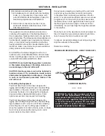
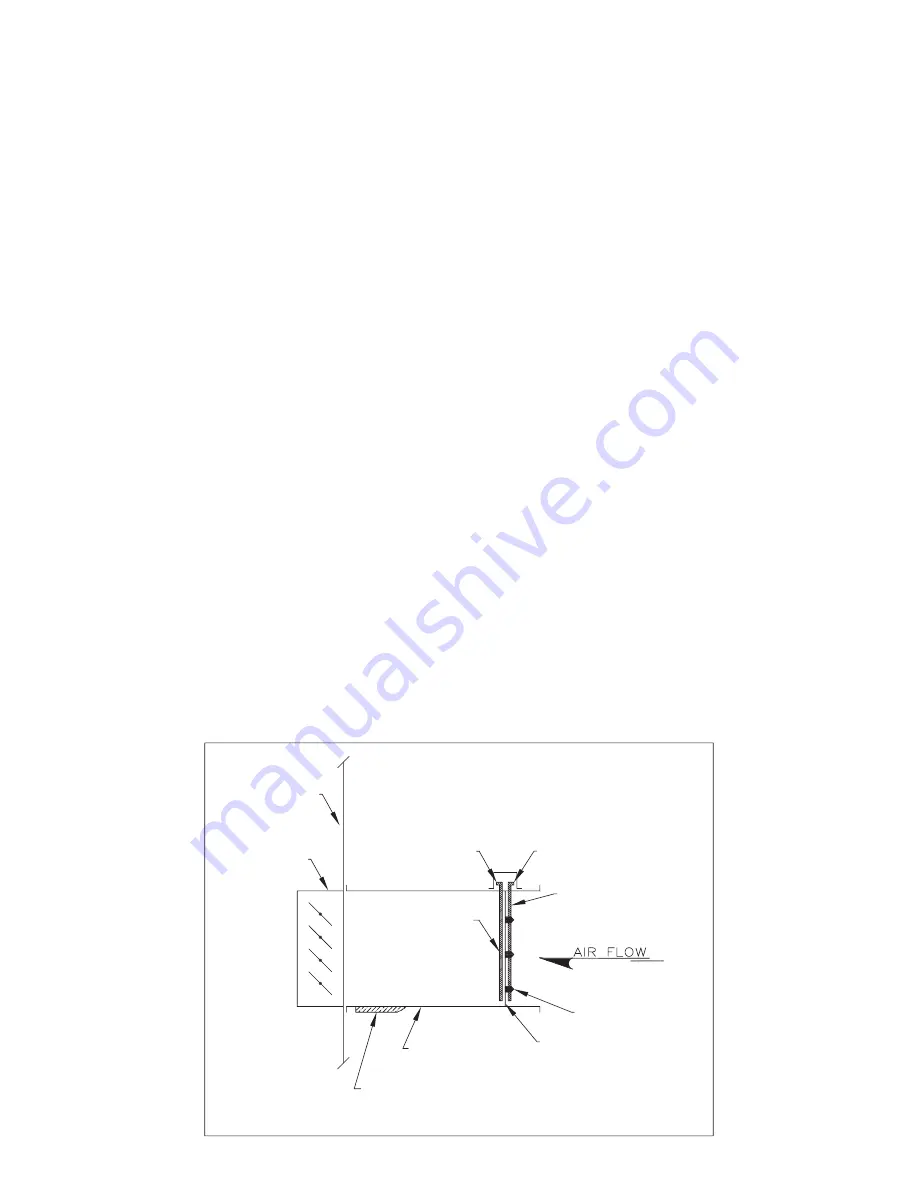
Flow Station Transducer Piping (PT-15)
Pipe the high side to the upstream connection and
low side to the downstream connection of the Air
fl
ow
Station as shown in Drawing # C000643 below. Be
sure that all tubing is clean and clear of any debris
before installing tubes on the transducer.
G. Field Wiring and Remote Control Installation
1. Connect the power lines to the line side of
the power distribution block or optional main
disconnect switch.
2. Field wiring is typically indicated on the wiring
diagram as dashed lines. When running any
fi
eld
wiring for control circuit be sure wire is sized for
a maximum 10% voltage drop. Check the VA
rating of control circuit transformer to determine
maximum load.
3. Mount and wire remote control panel, thermostats,
temperature sensors, and any other
fi
eld installed
controls as indicated on the unit control wiring diagram.
4. Connect all wires to the appropriate
fi
eld wiring
terminals and any shielded or twisted wires as indicated
on the unit control diagram.
5. Field wiring shall have a temperature rating of at
least 105°C. The minimum size of the supply cable
circuit shall be suf
fi
cient for the maximum ampacity
of the heater.
L'installation éléctrique d'utilisateur aura une
température qui évalue d'au moins 105°C. La
minimum de source du circuit de câblage sera
suf
fi
sante pour le ampacity maximum de l'appareil
de chauffage.
H. Locating Temperature Controls
The room or outdoor sensors should be mounted
where they will not be subjected to direct impact of
the heated air or radiant heat from the sun. It is also
recommended that thermostats, especially those with
mercury bulb contacts, be mounted on a vibration free
surface. The side of building columns away from the
heater or interior walls are usually the location best
suited for mounting thermostats.
Controls with outdoor sensors require that the outdoor
sensor be shielded from direct radiation from the sun. Unit
mounted sensors are factory located and mounted.
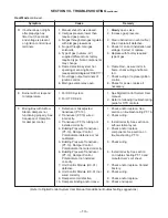
AMPLIFIER WING
(SHEET METAL STRIP)
TOTAL PRESSURE
SENSING TUBE
BULLET
STATIC PRESSURE
SENSING TUBE
HIGH PRESSURE
TUBE CONNECTION
LOW PRESSURE
TUBE CONNECTION
AIRFLOW STATION LAYOUT
C000643
AIRFLOW STATIO N
EXTERIOR INSULATION
FIELD PROVIDED WHEN
MOUNTED OUTDOORS
RA DAMPER
HEATER
CASING
NOTE: RUN TUBE CONNECTIONS
TO TRANSDUCER (PT-15) IN
UNIT CONTROL ENCLOSURE


