31
GB/MT
preferable to those with slight deviations towards
the east.
Horizontal orientation:
The horizontal orientation of the solar cell depends
on the geographic latitude of the mounting location.
In central Europe, and angle of 30°–40° is ideal.
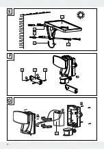
Drill 4 holes. Mount the solar cell by using
the dowel
21
(ø 6 mm) and screws
14
(ø 3.7 x 28 mm). To do so, use the pre-finished
mounting holes (see Fig. E).
After mounting, check that the solar cell is fitted
securely.
Note:
After mounting, orient the solar cell by
tilting it. The solar cell is fitted with a joint which
locks every 18° to permit orientation.
Preparing the product for use
Switching the motion detector
on and off
Slide the AUTO / OFF switch
4
into the AUTO
position to switch on the motion detector
6
.
Slide the AUTO / OFF switch into the OFF posi-
tion to switch off the motion detector.
Setting the lighting duration
Turn the rotary control TIME
10
on the bottom
of the motion detector
6
clockwise to increase
the duration of the illumination. The lighting
duration can be adjusted within a time window
of approx. 10–60 seconds.
Adjusting the sensitivity of
the sensor
Turn the rotary control SENS
9
on the bottom
of the motion detector
6
clockwise to in-
crease the sensitivity of the sensor.
Note:
The motion detector responds to heat
radiation. When outdoor temperatures are low,
it is more sensitive to body heat than when out-
door temperatures are warm. Be sure to regu-
late the sensitivity of the sensor over the course
of the year.
Setting the daylight level
Turn the rotary control LUX
8
on the bottom of
the motion detector
6
clockwise to increase
the daylight level. In position , the motion
detector only responds at pitch-black night
(approx. 50 lx). In position , the motion
detector also responds at daylight levels, as
long as about 20,000 lx are not exceeded.
Orientating the motion
detector
Loosen the fastening screws
5
of the motion
detector
6
.
Turn the rotary control LUX
8
to position .
Orient the motion detector into the central
region of the desired coverage area.
Move about through the coverage area until
you are satisfied with the response characteris-
tics of the motion detector. To find the proper
orientation, change the position of the rotary
control SENS
9
or the orientation of the
motion detector.
Re-tighten the fastening screws to fix the adjust-
ment.
Turn the rotary control LUX to the desired posi-
tion. These can be determined during the dawn
or twilight hours during which the spotlight
7
should respond. Slowly turn the rotary control
LUX clockwise until it reacts to movement within
the coverage area.
Содержание 40114
Страница 26: ...26 PT...
Страница 41: ...41 A max 12m 2 5 m B 1 19 2 3 7 4 5 8 6 9 10 6 D 2 11 12 39 9 0 39 9 0 5m 5m 12m 0 C...
Страница 42: ...42 E G 20 1 2 3 F 17 18 12 1 2 3 15 21 13 14 16...


