27
12.
Use a 14 mm end wrench to tighten the nut on the arc below and behind
the gear in position D.
13.
Use a 10 mm end wrench to tighten the nut that is on the back end of the
shaft in position B-C.
14.
Using 4 mm and 5 mm hex wrenches, tighten the three retaining socket
head cap screws on the ends of the shafts.
15.
Using a 4 mm hex wrench, replace the change gear cover.
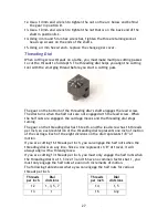
Threading Dial
When cutting screw threads on a lathe, you must make multiple cutting passes
to cut the threads to full depth. The threading dial helps you align the cutting
tool with the emerging thread before you start a cutting pass.
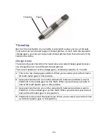
The gear on the bottom of the threading dial’s shaft engages the lead screw.
The dial turns when the half nuts are not engaged with the lead screw. When
the half nuts are engaged, the carriage moves and the threading dial stops
turning.
The gear on the threading dial has 16 teeth, and the lead screw has 16 threads
per inch, so each revolution of the threading dial represents one inch of motion
of the carriage. Each of the eight divisions on the dial represents 1/8” of
motion.
If you are cutting 16 threads per inch, you can engage the half nuts when the
threading dial is on any line. Since a line represents 1/8” of travel, it will
always align with a thread groove.
If you are cutting 13 threads per inch, you must only engage the half nuts when
the threading dial is at 1. Since 13 and 16 have no common factors but 1, you
must only engage the half nuts at even inch increments of motion.
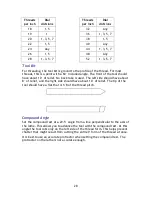
The following table shows where you can engage the half nuts for various
threads per inch.
Threads
per inch
Dial
divisions
12
1, 3, 5, 7
13
1
Threads
per inch
Dial
divisions
14
1, 5
16
Any


