


INTRODUCTION
EN
This instruction sheet provides you with the information required to safely own
and operate your product. Retain these instructions for future reference.
The product you have purchased is of the highest quality workmanship and
material, and has been engineered to give you long and reliable service. This
product has been carefully tested, inspected, and packaged to ensure safe
delivery and operation. Please examine your item(s) carefully to ensure that no
damage occurred during shipment. If damage has occurred, please contact the
place of purchase. They will assist you in replacement or repair, if required.
READ THESE INSTRUCTIONS CAREFULLY BEFORE ATTEMPTING
TO INSTALL, OPERATE, OR SERVICE YOUR PRODUCT. KNOW THE
PRODUCT’S APPLICATION, LIMITATIONS, AND POTENTIAL HAZARDS.
PROTECT YOURSELF AND OTHERS BY OBSERVING ALL SAFETY
INFORMATION. FAILURE TO COMPLY WITH THESE INSTRUCTIONS
COULD RESULT IN PERSONAL INJURY AND/OR PROPERTY DAMAGE!
DESCRIPTION
This pump is recommended for use in basins or lift stations and is suitable for
pumping sewage, effluent, wastewater, and other non-explosive, non-corrosive
liquids. It can handle 2” spherical solids.
Little Giant offers a complete line of control systems, along with a complete line
of alarms, basins, covers, and check valves.
SPECIFICATIONS
Discharge Size:
3”
FNPT
Handling Capabilities:
S Series: 2” spherical solids
Pump Housing:
Cast
iron
Volute:
Cast
iron
Impeller:
Non-clog brass with pressure relief vanes
Motor:
3-phase, 3200 RPM (control panel required)
Hardware:
300 Series stainless steel
Bearing:
Ball
Shaft Seal:
Mechanical, spring loaded, rotating carbon with Nitrile
boot and stationary ceramic seat, with secondary Nitrile
exclusion seal
Power Cord:
14 AWG 4-conductor, copper, stranded
Cooling:
The motor housing contains a cooling oil to provide
cooling for the motor and to lubricate bearings and
seals. These pumps are capable of operating with the
motor housing partially exposed for extended periods
of time, providing sufficient motor cooling and bearing
lubrication. However, for the best cooling and longest
motor life, the liquid level being pumped should normally
be above the top of the cast iron motor housing.
SAFETY GUIDELINES
WARNING: RISK OF ELECTRIC SHOCK.
THIS PUMP IS SUPPLIED WITH A
GROUNDING CONDUCTOR. TO REDUCE THE RISK OF ELECTRIC SHOCK,
BE CERTAIN THAT IT IS CONNECTED TO A PROPER ELECTRICAL GROUND.
DO NOT REMOVE CORD OR STRAIN RELIEF. DO NOT CONNECT CONDUIT
TO PUMP. THIS PUMP MUST BE INSTALLED BY QUALIFIED PERSONNEL.
1. Read all instructions and Safety Guidelines thoroughly. Failure to follow the
guidelines and instructions could result in serious bodily injury and/or property
damage.
2. DO NOT USE TO PUMP FLAMMABLE OR EXPLOSIVE FLUIDS SUCH
AS GASOLINE, FUEL OIL, KEROSENE, ETC. FAILURE TO FOLLOW
THIS WARNING CAN RESULT IN PERSONAL INJURY AND/OR PROPERTY
DAMAGE.
3. During normal operation the pump is immersed in water. Also, during rain
storms, water may be present in the surrounding area of the pump. Caution
must be used to prevent bodily injury when working near the pump.
4. Do not run the pump in a dry basin. If the pump is run in a dry basin, the
surface temperature of the pump will rise to a high level. This high level
could cause skin burns if the pump is touched and will cause serious damage
to your pump.
5. Do not oil the motor. The pump housing is sealed. A high grade dielectric
oil devoid of water has been put into the motor housing at the factory. Use
of other oil could cause serious electric shock and/or permanent damage
to the pump.
6. Do not install in locations classified as hazardous in accordance with the
National Electrical Code, ANSI/NFPA 70.
7. When a pump is in a basin, etc., do not touch motor, pipes or water until
unit is unplugged or shut off. If your installation has water or moisture
present, do not touch wet area until all power has been turned off. If shut-off
box is not accessible, call the electric company to shut off service to the
house, or call your local fire department for instructions. Failure to follow
this warning can result in fatal electrical shock.
8. The flexible PVC jacketed cord assembly mounted to the pump must not be
modified in any way, with the exception of shortening the cord to fit into a
control panel. Any splice between the pump and the control panel must be
made within a junction box and mounted outside of the basin, and comply with
the National Electrical Code. Do not use the power cord for lifting the pump.
INSTALLATION
This pump must be used with a control panel which incorporates thermal
or overload protection and stalled-rotor conditions and shall be rated or
set to a maximum ampere rating as noted below.
Refer to the instructions supplied with the control panel for all safety and installa-
tion procedures. Care should be taken to prevent pump running in a dry sump.
18S-CIM
CONTROL
VOLTS
AMPS
AMP
SETTING
230
11.5
16
MAX
460
5.3
10
MAX
200-208
13.5
16
MAX
Improper impeller rotation will result in damage to the pump. Rotation
must be checked at installation.
After completing the wiring and with the
disconnect switch in the “OFF” position, lay pump on the side to observe
the direction of rotation through the intake.
NOTE:
contact with pump when
energized could result in electrical shock. Turn disconnect switch to the “ON”
position momentarily. The impeller should be rotating counterclockwise. An
alternate method is to observe the kickback of the freely suspended pump as
it starts. The kickback should be in counterclockwise direction looking onto the
top of the pump. To change the direction of rotation, interchange any two of the
white, red, or black wires of the pump at the disconnect box.
Pump must be installed in a suitable gas tight basin which is at least 24” in
diameter and 36” deep, and vented in accordance with local plumbing codes.
Pump must be placed on a hard level surface. Never place pump directly on
clay, earth or gravel surfaces.
Pump can be installed with ABS, PVC, polyethylene or galvanized steel pipe.
Proper adapters are required to connect plastic pipe to pump.
Always install a union in the discharge line, just above the sump pit, to allow for
easy removal of the pump for cleaning or repair.
A check valve must be used in the discharge line to prevent back flow of liquid into
the basin. The check valve should be a free flow valve that will easily pass solids.
CAUTION:
For best performance of check valves, when handling solids install in a
horizontal position or at an angle of no more than 45º. Do not install check valve in
a vertical position as solids may settle in valve and prevent opening on start-up.
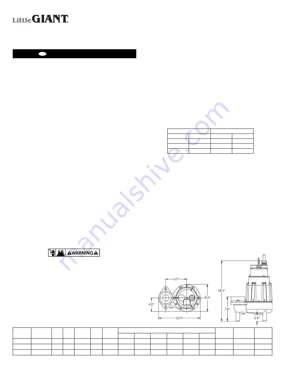
1
SUBMERSIBLE
SEWAGE EJECTOR
PUMP (3-PHASE)
MODEL 18S-CIM
Figure 1
MODEL
NO.
CATALOG
NO.
HP
PH
VOLTS
HZ
AMPS
GPM @ HEAD
SHUT
OFF (Ft.)
POWER
CORD (ft.)
WEIGHT
(lbs.)
10’
20’
30’
40’
50’
60’
18S-CIM
520302
1.5
3
200-208
60
13.5
160
137
111
84
50
15
64
20
96
18S-CIM
520303
1.5
3
230
60
11.5
160
137
111
84
50
15
64
20
96
18S-CIM
520304
1.5
3
460
60
5.3
160
137
111
84
50
15
64
20
96
Franklin Electric Co., Inc.
P. O. Box 12010
Oklahoma City, OK 73157-2010
405.947.2511 • Fax: 405.947.8720
www.LittleGiantPump.com
Содержание 18S-CIM
Страница 5: ...5 Figure 4...


