background image

Page ii

REV. 6-A-060818

PGR-3100 Ground-Fault Indication System

TABLE OF CONTENTS

1  FEATURES

 ....................................................................

1

2 DESCRIPTION

 ............................................................

1

3 INSTALLATION

 ..........................................................

1


4  TECHNICAL SPECIFICATIONS

.................................. 

4

LIST OF FIGURES

    1 

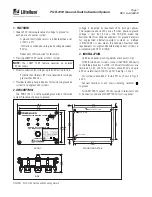
PGR-3100 Outline and Mounting Details .........

1


    2 

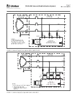
Connection Diagram for an Ungrounded 


240- to 600-V System .........................................

2

    3 

Connection Diagram for Ungrounded 


Systems above 600 V .........................................

2

    4 

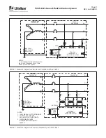
Connection Diagram for 


Resistance-Grounded System up to 600 V .......

3

    5 

Connection Diagram for a 


Resistance-Grounded System above 600 V .....

3

DISCLAIMER

Specifications are subject to change without notice.  

Littelfuse, Inc. is not liable for contingent or consequential 

damages, or for expenses sustained as a result of a mal-

function, incorrect application, or incorrect adjustment.

Содержание PGR-3100

Страница 1: ...00 832 3873 E mail techline littelfuse com www littelfuse com PGR 3100 Copyright 2018 Littelfuse All rights reserved Document P95 EPI0 00000 PGR 3100 MANUAL GROUND FAULT INDICATION SYSTEM Revision 6 A...

Страница 2: ...Page i REV 6 A 060818 PGR 3100 Ground Fault Indication System This page intentionally left blank...

Страница 3: ...ed 240 to 600 V System 2 3 Connection Diagram for Ungrounded Systems above 600 V 2 4 Connection Diagram for Resistance Grounded System up to 600 V 3 5 Connection Diagram for a Resistance Grounded Syst...

Страница 4: ...Page iii REV 6 A 060818 PGR 3100 Ground Fault Indication System This page intentionally left blank...

Страница 5: ...ets the Canadian Electrical Code requirements for ungrounded alternating current systems in accordance with CEC 10 106 2 3 INSTALLATION Outline and panel mounting details are shown in Fig 1 For 208 to...

Страница 6: ...MS UPTO 240 V USE H TERMINALS FOR SYSTEMS ABOVE 240 V UPTO 600 V TRANSFORMER ENCLOSURE SERVICE ENCLOSURE A B C 1 A 1 A 1 A AL AH BL BH CL CH L G 120 V LAMP TEST PGR 3100 GROUND FAULT INDICATION SYSTEM...

Страница 7: ...BOVE 240 V AND UPTO 600 V NOTE 1 TRANSFORMER ENCLOSURE SERVICE ENCLOSURE A B C 1 A 1 A 1 A AL AH BL BH CL CH 120 V LAMP TEST PGR 3100 GROUND FAULT INDICATION SYSTEM L G NEUTRAL GROUNDING RESISTOR PT S...

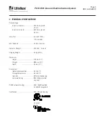
Страница 8: ...imum LED Threshold 30 Vac minimum Dielectric Strength 2 200 Vac 1 minute Shipping Weight 0 3 kg 0 8 lb Dimensions Height 108 mm 4 3 Weight 88 9 mm 3 5 Depth 54 mm 2 1 Environment Operating Temperature...

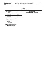
Страница 9: ...LEASE DATE MANUAL REVISION PRODUCT REVISION REVISION NUMBER ON PRODUCT LABEL June 08 2018 6 A 060818 03 March 09 2012 6 APPENDIX A PGR 3100 REVISION HISTORY MANUAL REVISION HISTORY REVISION 6 A 060818...

Отзывы: