


8
Full voltage and current are always present at the battery terminals. The batteries used in this system can produce
dangerous voltages, extremely high currents, and possible risk of electric shock. Batteries may cause severe injury if
the terminals are shorted together or to ground (earth). Be extremely careful to avoid electric shock and burns caused
by contacting battery terminals or shorting terminals during battery installation. Do not touch uninsulated battery
terminals.
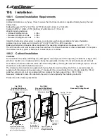
103.2 Installation Considerations
This section explains how to install the LiteGear system’s batteries and cables. A qualified electrician who is familiar
with battery installations and applicable building and electrical codes must install the batteries.
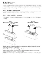
103.3 Battery Installation Procedure
Refer to Figures 103-1 and 103-2 depending on mounting configuration. For surface and recessed models install
and connect the low tier of batteries first. Next, install the shelf and the upper battery tier and make the final battery
connections.
Fig. 103-1
Surface and Recessed Wall Mount Models
Blue Leads to
PCT1 B- on PCB
Red Leads to
PCT3 B+ on PCB
Blue Leads to
PCT1 B- on PCB
Red Leads to
PCT3 B+ on PCB
Fig. 103-2
T-Grid Recessed Ceiling Model
CAUTION:
Be careful to observe correct polarity on the battery terminals. Illustrations are given as a guide only;
polarity markings may vary from battery to battery.
103.4 Electronics Cabinet Voltage Check
Using a digital volt-ohm meter, check for correct nominal battery voltage between battery NEG and POS wires.
Voltage reading should be 12 VDC ±10% of system DC voltage.
CAUTION:
Ensure all connections are fully engaged. Failure to do so may create an unsafe condition or fire hazard.


