


5
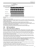
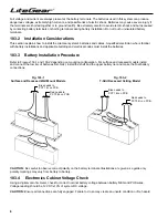
Fig. 100-4 – Chain/Cable Options for Ceiling Mount
A chain with a 50 lb. minimum working load or a cable with a 250 lb. minimum break strength is required to hang the ceiling unit in a T-Grid.
For example, the following can be used.
# 5 Double Loop Chain
# 10 Register Chain
# 8 Sash Chain
# 8 Single Jack Chain
3
/
64
" 7x7 Stainless Steel
Aircraft Cable
Fig. 100-4
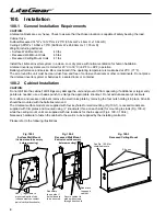
Recessed Ceiling Mount
Wall Mount Models: Once the cabinet is securely fastened to the wall, install and attach conduit using the knockouts
provided.
Install the input and output conduits.
AC Input service conductors and AC Output conductors must be run in separate conduits. LiteGear inverter system
emergency output circuits must be installed in dedicated conduit systems and not shared with other electrical circuits
as described in NEC 700-9(b).
Be sure to follow all federal, state, and local codes as it pertains to emergency circuit raceways.
For surface and recessed models reinstall the electronics plate and securely tighten the four mounting nuts.
For recessed mount models, adjust the trim plate to fit flush to the finished wall or ceiling surface. Adjust the LED/Test
Switch bracket to be flush with the cover when installed.
Connect the LEDs to the printed circuit board ensuring the connectors are properly aligned.
Connect the test switch to the printed circuit board ensuring both pin connectors are fully engaged.
101. AC Connections
101.1 General Precautionary Measures
All LiteGear inverter system units contain hazardous AC and DC voltages. Because of these voltages, a qualified
electrician must install the LiteGear inverter system, AC line service, and batteries. The electrician must install the AC
line service according to local, state and NEC codes and must be familiar with batteries and battery installation.
Before installing, maintaining, or servicing the unit, always remove or shut off all sources of AC and DC power and
shut off the LiteGear inverter system. Disconnect AC line input at the service panel and disconnect the batteries to
make sure the unit will not supply output voltage.
Whenever AC and/or DC voltage is applied, there will be AC voltage inside the LiteGear inverter system unit; the
unit can supply power from the AC line or from its batteries. To avoid equipment damage or personal injury, always
assume that there is voltage inside the LiteGear inverter system.
Remove rings, watches, and other jewelry before installing the AC wiring. Always wear protective clothing and eye
protection and use insulated tools when working near batteries. Whenever an energized unit is serviced with the cover
removed, electric shock is possible; follow all local safety codes.
TEST BEFORE TOUCHING!
To reduce the risk of fire or electric shock, install the LiteGear inverter system and the batteries in a temperature-
controlled and humidity-controlled indoor area free of conductive contaminants.
To prevent electrical shock or equipment damage, for all units, insure the AC input breakers at the service panel are
all off before making AC connections to the LiteGear inverter system.
The LiteGear inverter system is only designed to supply 120 VAC in/120 VAC out or 277 VAC in/277 VAC out. Only
authorized persons should disconnect AC to the unit. (See NEC 700-20 and 700- 21.)
Use of this equipment for simultaneous operation of 120VAC and 277VAC loads will damage the unit and void the
warranty.


