Note:
Each servo on the
Model 110
requires a servo wheel having a particular arm radius
(the distance from the arm center to one of the arm holes) in order to produce a
certain amount of pushrod travel. A large arm radius produces more pushrod travel
than a small radius. For each servo, select a servo wheel having arms with holes as
close as possible to the radius specified in the text. Place the wheel on the servo
output shaft so that one of the arms is angled as in the drawings, then trim off all the
other unused arms on the wheel. If you do not have a wheel with holes at the required
radius, drill a hole at the desired radius in any wheel you may have.
6.
q
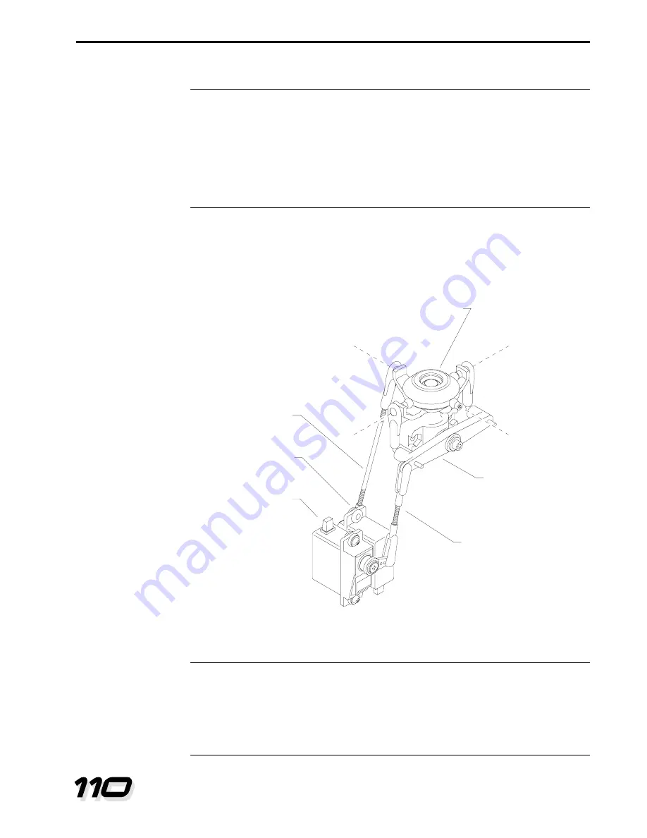
Find two servo wheels with holes at a radius of .44" to .47” (11mm to 12mm). Fit the
wheels to the left/right and fore/aft cyclic servos at the angles shown in Fig. 14-4. Trim all
unused arms off the wheels. Secure the servo wheels to the servos with servo wheel
screws (with the arms oriented as shown).
Note:
The angle between a pushrod and a servo arm (measured when the servos are
centered) affects pushrod motion. A pushrod that is 90 degrees to a servo arm will
travel the same distance in both control directions. A pushrod at an angle other than
90 degrees will travel more in one direction than the other. This effect is called
“differential throw”. Differential throw is useful on controls that need to move more in
one direction than in the other (such as the tail rotor).
Construction Manual
Pushrods and Radio Adjustment
LITE MACHINES
14-5
Left/right cyclic
pushrod
Left/right cyclic
servo
Fore/aft cyclic
servo
Swashplate
Pitch control arm
Fore/aft cyclic
pushrod
Level
Level
Figure 14-5.


