


page 60
02.47 CRANKSHAFT MAIN BEARINGS
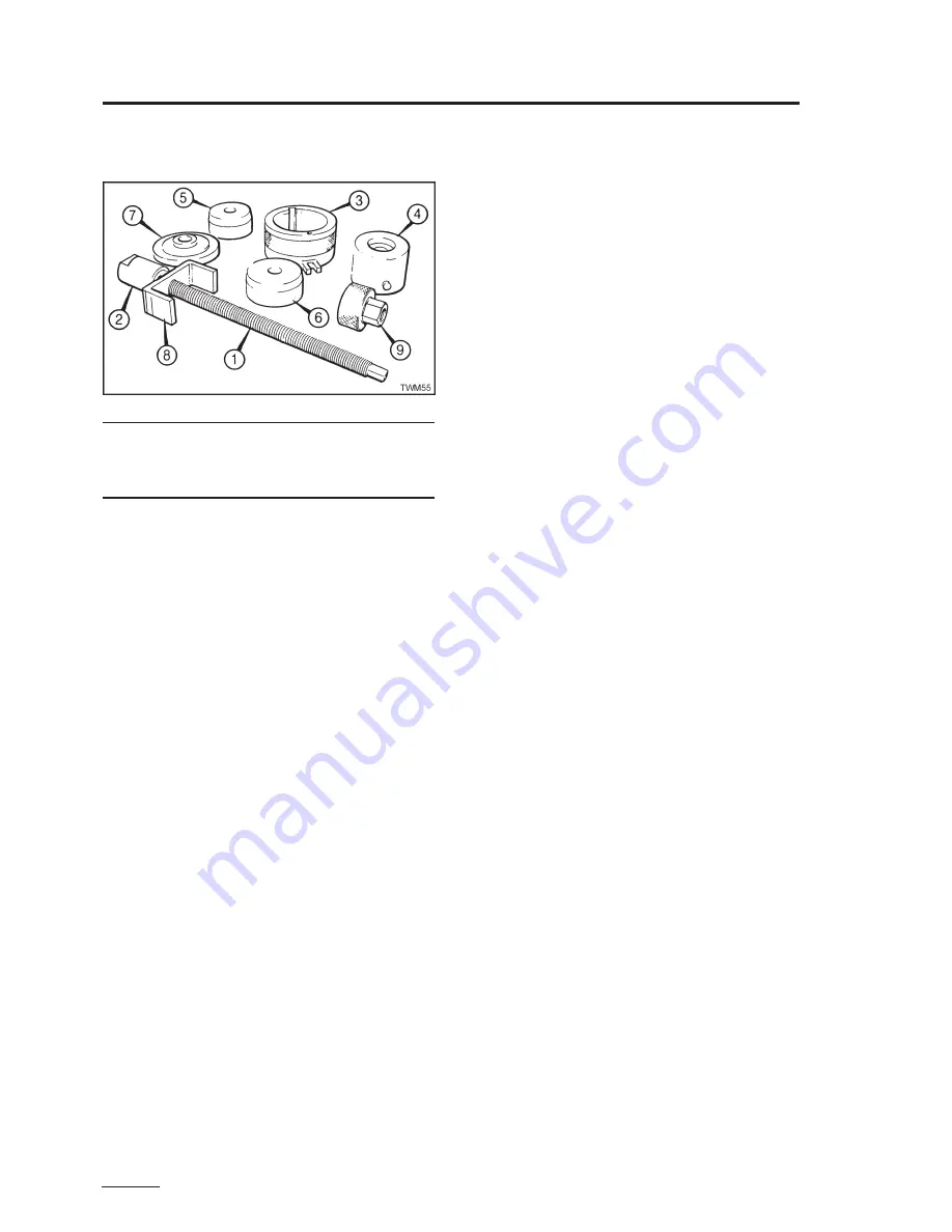
Main Bearing Tool 393235
Figure 2.47.1 Main Bearing Tool
Note:
This tool replaces 317-50006; both are described and
either can be used. The legend numbers referred to in
the illustration and text are also marked on the individual
tool components.
Gear End Main Bearing Removal
1. Fit the nut (2) onto the screw (1).
2. Place both dollies (5, 6) onto the screw with the
tapered ends outwards and the large dolly (6) next
to the nut (2).
3. Insert the assembly into the main bearing from
inside the crankcase.
4. Fit the bridge (8) followed by the thrust nut (9) onto
the screw (1).
5. Locate the bridge against the outside of the
crankcase
6. Using the correct size of spanner tighten the thrust
nut (9) until the main bearing shells are removed
from the crankcase.
Gear End Main Bearing Replacement
1. Remove the thrustwashers from the crankcase.
2. Fit the nut (2) and bridge (8) onto the screw (1).
Ensure the tang on the nut is correctly located
into the slot on the bridge.
3. Place both halves of the new bearing into the sleeve
(3) from the end opposite the locating spigots.
Align the ends of the new bearings with the letter
'G' on the sleeve and ensure the bearing oil hole is
correctly lined up with the '0' mark on the sleeve
face.
4. Place the dolly (6) with the taper outwards into the
spigot end of the sleeve (3).
5. Fit the driver (4) into the other end of the sleeve,
ensuring the guide dowel is positively located in
the slot in the sleeve.
6. Fit the assembly onto the crankcase from the
outside making sure the forked sleeve spigot is
fully located on the crankcase lower end cover
dowel.
7. Place the screw assembly inside the crankcase
and fit it to the sleeve assembly.
8. Place the depth plate (7) onto the screw with the
'G' face next to the driver (4).
Section 02
Engine Servicing and Adjustments
- crankshaft main bearings
9. Fit the thrust nut (9).
10.Using the correct size of spanner tighten the thrust
nut (9) until the depth plate is tight to the sleeve.
When the plate is tight to the sleeve the bearing
shells are correctly located in the crankcase.
11. Remove the tool taking care to prevent it dropping
onto the new bearing.
12.Check that the oil holes in the crankcase and
bearings align.
Flywheel End Main Bearing Removal
1. Remove the thrustwashers and the oil seal from
the bearing housing.
2. Fit the nut (2) onto the screw (1).
3. Hold the nut firmly across its flats in a vice.
4. Place both dollies (5, 6) onto the screw with the
tapered ends outwards and the large dolly (6) next
to the nut (2).
5. Fit the bearing housing on the screw with the thrust
face uppermost.
6. Fit the bridge (8) followed by the thrust nut (9) onto
the screw (1).
7. Using the correct size of spanner tighten the thrust
nut (9) until the main bearing shells are removed
from the bearing housing.
8. Remove the tool.
Flywheel End Main Bearing Replacement
The top half of the plain bearing in the main bearing
housing has a locating tongue which locates into its
recess in the main bearing housing when fully fitted.
1. Fit the nut (2) onto the screw (1).
2. Hold the nut firmly across its flats in a vice.
3. Place both halves of the new bearing into the sleeve
(3) from the end opposite the locating spigots.
Ensure the tag on the top half of the new bearings
faces outwards and is correctly located in the slot
in the sleeve and check that the ends of the
bearings line up with the 'F' mark on the sleeve.
4. Place the dolly (6) with the taper outwards into the
spigot end of the sleeve (3).
5. Fit the driver (4) into the other end of the sleeve,
ensuring the guide dowel is positively located in
the slot in the sleeve.
6. Place the depth plate (7) onto the screw (1) with
the face marked 'F' uppermost.
7. Place the sleeve assembly onto the screw with
the driver (4) next to the depth plate (7).
8. Place the bearing housing onto the screw with the
thrust face downwards.
Ensure the sleeve spigot is located in the recess
in the bearing housing.
9. Fit the bridge (8) followed by the thrust nut (9) onto
the screw (1).
10.Using the correct size of spanner tighten the thrust
nut (9) until the depth plate (7) is against the sleeve.
When the depth plate is against the sleeve the
main bearing shells are correctly located in the
housing.
11. Remove the tool taking care to prevent it dropping
onto the new bearing.
Содержание TR1
Страница 1: ...TS TR TX Workshop Manual Edition 12 May 2005 Publication P027 08221 ...
Страница 2: ...page 2 ...
Страница 80: ...page 80 Section 05 Routine Maintenance TS TR wearing parts TS TR Wearing Parts ...
Страница 81: ...page 81 Section 05 Routine Maintenance TS TR wearing parts TS TR Wearing Parts ...
Страница 82: ...page 82 Section 05 Routine Maintenance TX wearing parts TX Wearing Parts ...
Страница 83: ...page 83 Section 05 Routine Maintenance TX wearing parts TX Wearing Parts ...
Страница 90: ...page 90 Section 07 Flywheel Charge Windings Syncro Syncro Fault Finding Flow Charts ...
Страница 91: ...page 91 Section 07 Flywheel Charge Windings Syncro Syncro Fault Finding Flow Charts ...
Страница 93: ...page 93 Nicsa Fault Finding Flow Charts Section 07 Flywheel Charge Windings Nicsa ...
Страница 94: ...page 94 Section 07 Flywheel Charge Windings Nicsa Nicsa Fault Finding Flow Charts ...
Страница 95: ...page 95 Section 07 Flywheel Charge Windings Nicsa Nicsa Fault Finding Flow Chart ...
Страница 96: ...page 96 ...
Страница 98: ...page 98 Section 08 Electrical Wiring Diagrams ...
Страница 99: ...page 99 Section 08 Electrical Wiring Diagrams ...
Страница 100: ...page 100 Section 08 Electrical Wiring Diagrams ...
Страница 101: ...page 101 Section 08 Electrical Wiring Diagrams ...
Страница 102: ...page 102 Section 08 Electrical Wiring Diagrams ...
Страница 103: ...page 103 Section 08 Electrical Wiring Diagrams ...
Страница 104: ...page 104 ...
Страница 115: ...page 115 Section 11 Index Section 11 Index a ...
Страница 121: ...Technical Library http engine od ua ...


