background image

8

AudioConnect

TM

 Manual

 Operation

Configure Listen Hardware

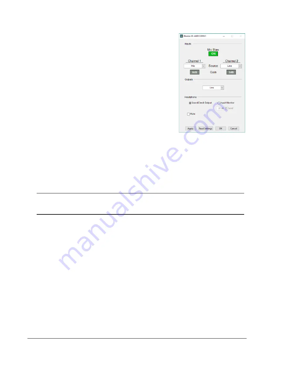
The Message Step for AudioConnect in 

Figure 4-3

 shows the default 

settings for AudioConnect.

Mic Bias

Turns the 9.5 VDC microphone bias On and Off for both 
microphone input channels

Gain

Select 0 dB or +20 dB independently for channels 1 & 2

Input select

Select Mic or Line Input independently for channels 1 & 2

SoundCheck Hardware Editor Vp values automatically adjust 
when AudioConnect input channels are switched between mic 
and line via Message steps in a sequence

Output select

The output should be set to Line

Digital Out is currently not available.

Headphone

SoundCheck Output

 - Allows you to monitor the Output of the audio interface at the Headphone 

jack. Use this setting if using the output for Headphone testing.

For use in headphone testing, the gain is fixed at 0.1 dB. The headphone out should be 
calibrated in the SoundCheck Calibration Editor. The Headphone Amp Calibration Sequence 
should be used. See

 Headphone Amp Calibration on page 5

.

Note:

Prior to serial number 40501270109, firmware 1.61, the headphone output polarity is inverted 
for both channels. Polarity tests using the headphone out will need to be adjusted accordingly. 
Polarity Limits may need to be changed from a Lower Limit of 0 to an Upper Limit of 0.

Input Monitor

 - Used to listen to the Input of the audio interface. Use this setting when verifying the 

signal coming into SoundCheck.

Monitor level default is approx -16 dB

Apply 

- Click to send the current setting to the device

Read Settings 

- Click to get the current settings of the connected device

OK/Cancel 

- Click to close the device editor or message step

OK accepts the changes

Cancel will ignore the changes and return to the previously saved state

For more information on the use of Message Steps in a SoundCheck, please refer to the Message Editor 
chapter of the SoundCheck Manual.

Analysis

AudioConnect requires that all Analysis Steps in SoundCheck sequences use Auto Delay on the Delay Tab. 

Figure  4-3:  Device Settings

Содержание AudioConnect Series

Страница 1: ...56 4104 Fax 617 556 4145 Web www listeninc com Sales sales listeninc com Support support listeninc com AudioConnect UserManual TM Listen Inc 580 Harrison Ave Suite 3W Boston MA 02118 Tel 617 556 4104...

Страница 2: ...Rev 030519...

Страница 3: ...edure 6 Operation 7 SoundCheck Control 7 Auto Mode OFF 7 Analysis 8 Front Panel 9 Back Panel 10 Recommended Cable Length 10 Connection Diagram 11 Loudspeaker Test using AudioConnectTM and SC AmpTM 11...

Страница 4: ...ii Contents AudioConnectTM Manual Page Intentionally Left Blank...

Страница 5: ...dling of the Products against defects or damages arising from improper installation where installation is by persons other than Manufacturer against defects in products or components not manufactured...

Страница 6: ...iv AudioConnectTM Manual Limited Warranty Page Intentionally Left Blank...

Страница 7: ...ion with no room for error The interface is supplied fully calibrated Features High quality professional audio interface Analog audio in and out 2 Channels In 2 Channels Out USB Controlled in SoundChe...

Страница 8: ...2 AudioConnectTM Manual Introduction Page Intentionally Left Blank...

Страница 9: ...are shown below Auto Mode As of SoundCheck 14 the Hardware Editor in SoundCheck can automatically read the Vp values from AudioConnect when the editor is set to Auto Mode Please refer to the SoundChe...

Страница 10: ...bs The Windows audio mixer must be set to 100 for both Level and Balance as shown in Figure 2 2 We also recommend that you set the mother board audio device or an audio channel not used for measuremen...

Страница 11: ...ivity is set to 5 8dB as a nominal value The following procedure allows you to calibrate the left and right channels of the headphone amp This will set the Sensitivity in the Calibration editor and cr...

Страница 12: ...select the channel that the output of the AudioConnect Headphone Amp L is routed to 6 Click Calibrate Device When prompted with wiring instructions use the example in Figure 3 2 Follow the sequence pr...

Страница 13: ...dware Editor It also requires that discreet hardware input channels are created for Mic In 1 and 2 as well as Line In 1 and 2 These channels should have the specific Vp values for each channel These c...

Страница 14: ...n Editor The Headphone Amp Calibration Sequence should be used See Headphone Amp Calibration on page 5 Note Prior to serial number 40501270109 firmware 1 61 the headphone output polarity is inverted f...

Страница 15: ...the Sound Card calibration process on the microphone inputs or when running Self Test LED Level Indicators Off Output level is less than 50 dBFS Green Output level is between 50 dBFS and 3 dBFS Yellow...

Страница 16: ...b Connector The USB Full Speed connector is for Hardware Keys keyboards mice and control of devices such as SoundConnect 2 It is not for use with hard drives memory sticks or audio interfaces Internal...

Страница 17: ...el settings See SoundCheck Control on page 7 AudioConnect Output 1 to SC Amp Line Input Balanced connection recommended SC Amp 0 1 V A Impedance Interface Output to AudioConnect Input 2 Balanced conne...

Страница 18: ...ip Sleeve cable requires the use of Single Ended Vp values in the SoundCheck Hardware Editor Example 2 This option allows you to still use Balanced Vp values in the Hardware Editor Example 3 While thi...

Страница 19: ...Block Diagram AudioConnectTM Manual 13 Block Diagram...

Страница 20: ...14 AudioConnectTM Manual Block Diagram Page Intentionally Left Blank...

Страница 21: ...ur devices can be mounted on the shelf as shown Each Connect Series device is attached to the shelf with four 4 40 x 1 4 Phillips flat head machine screws included Mounting Remove the rubber feet from...

Страница 22: ...16 AudioConnectTM Manual Connect Series Hardware Shelf Mounting Instructions page intentionally left blank...

Страница 23: ...0 kHz 0 1 0 25 dB Frequency Response 3 0 dB 5 Hz to 20 kHz Maximum Input Voltage 5 15 Vp 0 dB Gain Input Impedance 7 5 k Bias On THD N 1 kHz 86 dB 0 005 1 kHz 20 to 20 kHz BW Selectable Gain 0 03 dB 0...

Страница 24: ...osstalk 1 kHz 60 dB 1 kHz 20 Hz to 20 kHz BW Minimum Load 16 Output Connector 1 4 TRS Headphone Jack USB Interface Inputs 2 Individually selectable between mic input and line input Outputs 2 shared be...

Страница 25: ...ved AC power adapter Transient Overvoltages up to the levels of Overvoltage Category II as required in the relevant standards listed on the Declaration of Conformity Temporary Overvoltages occurring o...

Страница 26: ...20 Declaration of Conformity AudioConnectTM Manual Declaration of Conformity...

Страница 27: ...pport support listeninc com 580 Harrison Ave Suite 3W Boston MA 02118 617 556 4104 Fax 617 556 4145 www listeninc com Listen Inc 2014 2018 All rights reserved SoundCheck HarmonicTrak STWEEP SoundCheck...

Отзывы: