background image

A-1

A-1

INSTALLATION

Fuse or

Output Mode

Input Voltage

Breaker Size

Input Amps

Power Cord

RATED

240V/50Hz

25 Super Lag

12.7

15Amp, 240V,

Three Pin Plug

TECHNICAL SPECIFICATIONS – Handymig 170i

INPUT – SINGLE PHASE ONLY

RATED OUTPUT

OUTPUT

RECOMMENDED INPUT CABLE AND FUSE SIZES

Height

Width

Depth

Weight

305 mm

248 mm

419 mm

25.9 kg

PHYSICAL DIMENSIONS

Standard Voltage/Frequency

AS

1966.1

240V/50Hz

Rated Input Current

12.7 Amps 

Duty Cycle

Amps

Volts at Rated Amperes

20%

130

20

Welding Current Range

Maximum Open Circuit Voltage

Auxiliary Power

Rated DC Output:  30 – 170 amps

33

N/A

Handymig 170i

Содержание Handymig 170i

Страница 1: ... ING THIS MANUAL AND THE SAFETY PRECAUTIONS CON TAINED THROUGHOUT And most importantly think before you act and be careful For use with machine Code Numbers 10984 A Division of Lincoln Electric Company Aust Ply Ltd A B N 36 000 040 308 Copyright 2000 Lincoln Global Inc 35 Bryant Street Padstow NSW2211 Australia Made exclusive for Australia This manual covers equipment which is no longer in product...

Страница 2: ...TOR BEFORE OPERATING For more detailed information it is strongly recommended that you purchase a copy of Safety in Welding and Cutting ANSI Standard Z49 1 and WTIA Technical Note 7 All WTIA publications and ANSI AWS Standards are available from the Welding Technology Institute of Australia PO Box 6165 Silverwater NSW 2128 For copies of various Australian Standards contact your local S A A office ...

Страница 3: ... significantly affects the degree to which it is subject to interference from a welding circuit Do not rely on the fact that you know another welder with a pacemak er who has welded for years without experiencing a prob lem That welder and his or her pacemaker may be quite different from you and your pacemaker ELECTRIC AND MAGNETIC FIELDS may be dangerous 2 a Electric current flowing through any c...

Страница 4: ...rical earth ground 3 f Maintain the electrode holder work clamp welding cable and welding machine in good safe operating condition Replace damaged insulation 3 g Never dip the electrode in water for cooling 3 h Never simultaneously touch electrically hot parts of electrode holders connected to two welders because voltage between the two can be the total of the open circuit voltage of both welders ...

Страница 5: ... the welding sparks from starting a fire Remember that welding sparks and hot materials from welding can easily go through small cracks and openings to adjacent areas Avoid welding near hydraulic lines Have a fire extinguisher readily available 6 b Where compressed gases are to be used at the job site special precautions should be used to prevent hazardous situations Refer to Safety in Welding and...

Страница 6: ...e of the building and other activities that are taking place The surrounding area may extend beyond the boundaries of the premises Methods of Reducing Emissions Mains Supply Welding equipment should be connected to the mains supply according to the manufacturer s recommendations If interference occurs it may be necessary to take additional precautions such as filtering the mains supply Considerati...

Страница 7: ...ation below for future reference This information can be found on your machine nameplate Product _________________________________________________________________________________ Model Number ___________________________________________________________________________ Code Number or Date Code_________________________________________________________________ Serial Number_____________________________...

Страница 8: ...on for Rated Output A 6 Line Cord Connection A 6 Operation Section B Safety Precautions B 1 General Description B 1 Recommended Processes B 1 Optional Features and Controls B 1 Design Features and Advantages B 1 Welding Capability B 2 Limitations B 2 Controls and Settings B 2 Welding Operations B 3 Sequence of Operations B 3 Wire Loading B 3 Friction Brake Adjustments B 3 Wire Threading B 4 Making...

Страница 9: ...Tips Nozzles and Gun Tubes D 1 Component Replacement Procedures D 2 Changing the Contact Tip D 2 Changing Drive Roll D 2 Changing Liner D 3 Gun Handle Parts D 3 Ground Test Procedure D 4 Troubleshooting Section E Safety Precautions E 1 How to Use Troubleshooting Guide E 1 Troubleshooting Guide E 2 thru E 4 Wiring Diagrams Section F Handymig 170i Wiring Diagram F 1 Handymig 170i Parts P463 P202 P18...

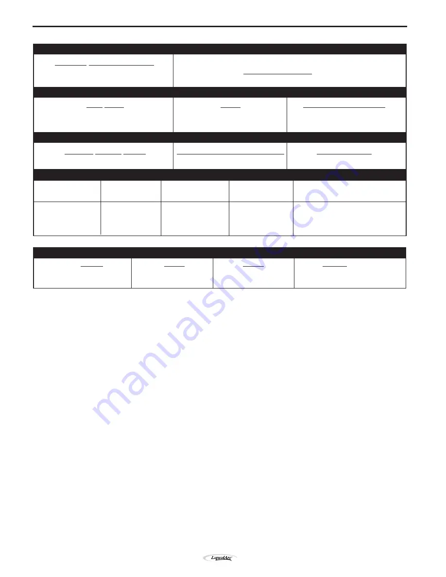
Страница 10: ...T SINGLE PHASE ONLY RATED OUTPUT OUTPUT RECOMMENDED INPUT CABLE AND FUSE SIZES Height Width Depth Weight 305 mm 248 mm 419 mm 25 9 kg PHYSICAL DIMENSIONS Standard Voltage Frequency AS1966 1 240V 50Hz Rated Input Current 12 7 Amps Duty Cycle Amps Volts at Rated Amperes 20 130 20 Welding Current Range Maximum Open Circuit Voltage Auxiliary Power Rated DC Output 30 170 amps 33 N A Handymig 170i ...

Страница 11: ...4 10 ft 3 0 m work cable 5 Work clamp 6 Adjustable mixed Gas Regulator Hose 1 The gun is ready to feed 023 025 0 6 mm diameter wire ELECTRIC SHOCK can kill Only qualified personnel should perform this installation Only personnel that have read and under stood the Handymig 170i Operating Manual should install and operate this equipment Machine must be plugged into a receptacle which is grounded per...

Страница 12: ... on the recommended cart The machine may topple over if this procedure is not fol lowed OUTPUT CONNECTIONS Refer to Figure A 2 1 Work Cable Access Hole 2 Gun Cable and Control Lead Access Hole 3 Connector Block 4 Gun Trigger Lead Connectors 5 Positive and negative output terminals 6 Wire Feed Gearbox 7 Cable Hanger 8 Thumbscrew Work Clamp Installation Attach the work clamp per the following Refer ...

Страница 13: ...se front behind the gas line 3 Insert the connector on the gun conductor cable through the Gun Cable Access Hole 2 in the Handymig 170i case front Make sure the connec tor is all the way in the brass connector block to obtain proper gas flow If the gun connector will not fully insert unscrew the thumbscrew on the con nector block a few turns Rotate the connector so control leads are on the undersi...

Страница 14: ... may explode if dam aged Keep cylinder upright and chained to support Keep cylinder away from areas where it may be damaged Never lift welder with cylinder attached Never allow welding electrode to touch cylinder Keep cylinder away from welding or other live electrical circuits BUILDUP OF SHIELDING GAS may harm health or kill Shut off shielding gas supply when not in use 1 Chain the cylinder to a ...

Страница 15: ...work Line Cord Connection A three conductor line cord with a 15 amp 240 volt three pin plug is factory installed Connect this plug to a mating grounded receptacle which is connected to an appropriate power supply per the Wiring Rules and any applicable local codes This welding machine must be connected to a power source in accordance with applicable electrical codes If there is any question about ...

Страница 16: ...venient chart is mounted inside the wire feed section door for setting welding procedures for 24 gauge 60 mm through 5 16 8 0 mm mild steel The machine is rugged and reliable and has designed for dependable service and long life RECOMMENDED PROCESSES The Handymig 170i can be used for welding mild steel using the GMAW single pass process which requires a supply of shielding gas or it can be used wi...

Страница 17: ... of the machine The welding output and wire feeder remain off until the gun trigger is pressed 2 Wire Speed Control Controls the wire feed speed from 50 400 in min 1 2 10 2 m min The control can be preset on the dial to the setting specified on the Handymig 170i Application Chart located on the inside of the wire feed section door 3 Voltage Control A 5 posi tion tap selector switch gives full rang...

Страница 18: ...ool is mounted directly on the 5 8 16 mm diameter shaft and held in place with the previously removed hardware Also make certain the start end of the wire which may pro trude through the side of the spool does not contact any metallic case parts Note The brake should be adjusted with a spool of wire installed When properly adjusted it should move freely but not coast Some spools can have the start...

Страница 19: ...ustment counter clockwise to reduce distortion of the wire Slightly less pressure may be required when using 0 023 0 025 0 6 mm wire If the 6 drive roll slips while feeding wire the pressure should be increased until the wire feeds properly When inching the welding wire the drive rolls the gun connector block and the gun contact tip are electrically energized relative to work and ground and remain...

Страница 20: ...trigger and then pull the gun away from the work after the arc goes out FIGURE B 6 10 When no more welding is to be done close valve on gas cylinder if used momentarily operate gun trigger to release gas pressure and turn off the Handymig 170i Cleaning Tip And Nozzle Clean the contact tip and nozzle to avoid arc bridging between the nozzle and contact tip which can result in a shorted nozzle poor ...

Страница 21: ...llation in INSTALLATION section for changing the polarity Use optional Innershield welding kit K549 1 for 0 9 mm or K549 2 for 1 2 mm as appropriate K549 1 0 9mm 035 Innershield Welding Kit Includes a contact tip a gasless nozzle and a 0 9 1 2mm cable liner to permit the Magnum 100L gun and cable to use 0 9mm diameter flux cored elec trode The fitting on the end of the liner is stencilled with the...

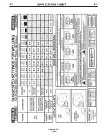
Страница 22: ...B 7 B 7 APPLICATION CHART Handymig 170i ...

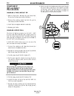
Страница 23: ...de of the contact tip and screw it snugly into the gas diffuser Remove spatter from inside of gas nozzle and from tip after each 10 minutes of arc time or as required Be sure the gas nozzle is fully screwed onto the diffuser for gas shielded processes For the Innershield process the gasless nozzle should be screwed onto the diffuser CAUTION D 1 MAINTENANCE SAFETY PRECAUTIONS ELECTRIC SHOCK can kil...

Страница 24: ...g loaded pressure arm and lift the idle roll arm away from the drive roll 3 Turn the power switch to ON marked I 4 Set the wire speed to minimum and jog the drive unit with the trigger switch until the drive roll set screw is facing up When inching the welding wire the drive rolls gun connector block and gun contact tip are energized relative to work and ground and remain energized for several sec...

Страница 25: ...ter clockwise 3 Remove the gas diffuser from the gun tube by unscrewing counter clockwise 4 Lay the gun and cable out straight on a flat surface Loosen the set screw located in the brass connec tor at the wire feeder end of the cable Pull the liner out of the cable 5 Insert a new untrimmed liner into the connector end of the cable Be sure the liner bushing is stenciled appropriately for the wire s...

Страница 26: ...sistance 1M Welding circuit test Connect one lead of the mega tester to the frame of the machine and the other lead to the positive output stud Apply the test Minimum resistance 1M Auxiliary circuit test Connect one lead of the mega tester to the frame of the machine and the other lead to jumper on pins 4 5 in the shorting socket Apply the test Minimum resistance 1M Input circuit to welding circui...

Страница 27: ...ted with out removing the case wrap around cover Step 3 PERFORM COMPONENT TESTS If you have exhausted all of the recom mended tests in Step 2 Consult your Local Authorized Field Service Facility HOW TO USE TROUBLESHOOTING GUIDE Service and Repair should only be performed by Liquid Arc Factory Trained Personnel Unauthorized repairs performed on this equipment may result in danger to the technician ...

Страница 28: ...certain that power switch is in the ON position 3 Make sure circuit breaker is reset 1 The thermostat may be tripped due to overheating Let machine cool Weld at lower duty cycle 2 Check for obstructions in air flow 3 Check Gun Trigger connections See Installation section 4 Gun trigger may be faulty RECOMMENDED COURSE OF ACTION If all recommended possible areas of misadjustments have been checked a...

Страница 29: ...chine 2 Check for clogged cable liner or contact tip 3 Check for proper size cable liner and contact tip 1 Check gas supply flow regulator and gas hoses 2 Check gun connection to machine for obstruction or leaky seals RECOMMENDED COURSE OF ACTION If all recommended possible areas of misadjustments have been checked and the problem persists contact your local Liquid Arc Authorized Field Service Fac...

Страница 30: ...to machine See Installation sec tion Electrical Input Connections 2 Check for proper electrode polarity for process 3 Check gun tip for wear or dam age and proper size Replace 4 Check for proper gas and flow rate for process For MIG only 5 Check work cable for loose or faulty connections 6 Check gun for damage or breaks 7 Check for proper drive roll orien tation and alignment 8 Check liner for pro...

Страница 31: ...10984 Handymig 170i WIRING DIAGRAM 10 00 NOTE This diagram is for reference only It may not be accurate for all machines covered by this manual The specific diagram for a particular code is pasted inside the machine on one of the enclosure panels Handymig 170i ...

Страница 32: ...NOTES ...

Страница 33: ...NOTES ...

Страница 34: ...electrically live parts or electrode with skin or wet clothing Insulate yourself from work and ground No toque las partes o los electrodos bajo carga con la piel o ropa moja da Aislese del trabajo y de la tierra Ne laissez ni la peau ni des vête ments mouillés entrer en contact avec des pièces sous tension Isolez vous du travail et de la terre Berühren Sie keine stromführenden Teile oder Elektrode...

Страница 35: ...gute Be und Entlüftung des Arbeitsplatzes Mantenha seu rosto da fumaça Use ventilação e exhaustão para remover fumo da zona respiratória Turn power off before servicing Desconectar el cable de ali mentación de poder de la máquina antes de iniciar cualquier servicio Débranchez le courant avant l entre tien Strom vor Wartungsarbeiten abschalten Netzstrom völlig öff nen Maschine anhalten Não opere co...

Страница 36: ...A Division of Lincoln Electric Company Aust Ply Ltd A B N 36 000 040 308 Copyright 2000 Lincoln Global Inc 35 Bryant Street Padstow NSW2211 Australia ...

Отзывы: