Rev: 08.17.21
Page 5
CCD-0004406
Fig. 4
B
A
4.
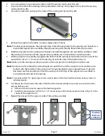
Use a screwdriver to spread open either end of the awning rail channel (Fig. 4A).
5.
To protect the fabric from damage during installation, file any sharp edges or burrs from the awning
rail channel (Fig. 4B).
6.
Use silicone lubricant and spray the inside of the awning rail channel (Fig. 4B).
Fig. 5
Fig. 6
Possible
Fastener
Locations
Fig. 7
7.
Remove the tape from the fabric. Unroll a small portion of fabric
Note:
The next steps will require three people: One to feed the polycord into the awning rail channel; two
to walk the support arm assemblies along the awning rail while the fabric slides into position.
8.
Slide the polycord into the awning rail channel and walk the support arm assemblies and fabric down
the awning rail channel until the support arm assemblies are in line with the centerline marks.
9.
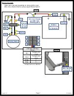
Lift the support arm assembly up against the bottom of the awning rail and attach it to the side of the
unit with two #14 x 1 1/4" screws at the top (Fig. 5) and one screw at the bottom (Fig. 6).
Note:
Make sure the awning assembly is square on the unit prior to mounting the bottom screw.
Note:
Best practice for setting the awning height is to push the top of the support arm assemblies up to
be flush with the bottom of the awning rail. The awning height can be adjusted lower if desired,
but make sure that the distance from the awning rail to the top of the support arm assemblies is
consistent at both ends of the awning.
Note:
Four rivets with 3/16" grip range can be used in place of the two middle and two lower screws on
laminated walls.
10. Cut the zip ties and connect the wires from the drive head assembly to a power source and run the
awning half way out.
A. Remove the wire cover to expose the fastening points.
B. Install the remaining two (2) #14 x 1 1/4” screws at any of the three locations shown (Fig. 7) in the
center of the support arm.
11. Repeat this process for the opposite side of the awning assembly.


