


LinMot
Design and Installation
User Manual V1.01
4-15
Starts the “Emergency Stop” behavior that was specified. Here it can specified whether
the slider should be stopped with the maximal allowed acceleration, taken to a
predefined emergency stop position or the motor should be turned off.
Data:
Galvanically separated digital input (Low level active)
Input voltage:
0…24V DC (max. -10…26V DC)
For signal = 0
< 2V DC
For signal = 1
> 3.5V DC
Input
current:
<
20mA
(24V)
Input
delay:
1.6ms
The sliders of the linear motors are stopped with the maximal allowed acceleration.
Data:
Galvanically separated digital input (High level active)
Input voltage:
0…24V DC (max. -10…26V DC)
For signal =0
< 2V DC
For signal =1
> 3.5V DC
Input
current:
<
20mA
(24V)
input
delay:
1.6ms
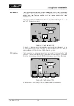
The digital outputs are realized as open collector outputs and must be driven over an
external pull-up resistor.
Figure 4-13: Digital output layout
During normal operation (no warnings or error messages) the digital outputs are pulled
down to ground (GND) by the electronic unit. When an error or a warning is generated
(or the signal cable is interrupted) the output becomes high impedance and is pulled up
over the external resistor.
This is set when a warning (to be considered) is pending. A warning is to be considered
as a precursor of an error.
Data:
Open collector output (High level active)
Max. 24V / 20mA
This output is set when an error has occurred, that should be taken care of.
Data:
Open collector output (High level active)
Max. 24V / 20mA
This output is set when the slider is outside the position range that was defined for it.
Data:
Open collector output (High level active)
Max. 24V / 20mA
STOP
FREEZE
Digital outputs
WARNING OUT
ERROR OUT
POSITION
ERROR OUT