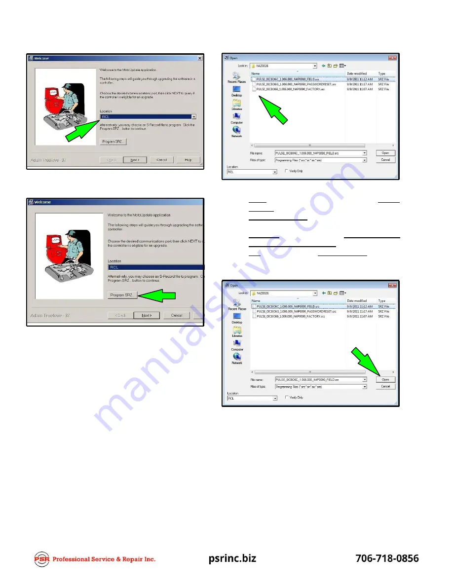
Link-Belt PULSE Скачать руководство пользователя страница 67


24.


Select the programming location for  “RCL”. 


26.


Select the file to be programmed. 
a.


FIELD  –  use  this  file  to  update  software.  No cal- 
ibration  required. 

b.


PASSWORDRESET  –  use  this  file  to  reset  the 
default factory passwords. 

c.


FACTORY – use this file when directed to do so 
by the version description. This file will erase 
ALL calibration data. Full calibration will be re- 
quired. 


25.


Click the “Program SRZ”  button. 


27.


Click “Open”. 

Содержание PULSE

Страница 1: ...Link Belt Pulse Calibration Manual Level 2 Access on Cranes with Outrigger Sensors Link Belt is a registered trademark ...

Страница 2: ......

Страница 3: ......

Страница 4: ...Link Belt Pulse Calibration Manual ...

Страница 5: ...ion 11 Pressure Programming 12 Program Pressure Transducers 12 Reset Pressure Transducers 13 Outrigger Programming And Calibration 14 Hydraulic Fly Angle Sensor Calibration 16 Main Winch Friction Calibration 18 Auxiliary Winch Friction Calibration 22 Bias And Slope Sliders Explanation 24 Fly Weight Calibration Fly Erected 25 Fly Weight Calibration Fly Stowed 27 Diagnostics 29 CAN Viewer 29 Active ...

Страница 6: ...35 Winch 36 Misc 37 Front Winch Rope Capacity 38 Rear Winch Rope Capacity 38 About 39 Appendix A 40 Friction And Dynamic Calibration 40 Appendix B 45 HED Programming Instructions 45 Appendix C 54 ECM Programming Instructions 54 ...

Страница 7: ...to allow full extension of all boom sections REFERTOTHECRANERATINGMANUALFOR SAFE OPERATION 3 If software is to be updated record ALL Friction Slider Bar Values BEFORE programming any of the Electronic Control Modules ECM s Display Button Identification 1 The Buttons on the actual Pulse Display are not numbered but for the purpose of this document Buttons 1 through5 starting on theleft will beref e...

Страница 8: ...er of the Password and press Button 3 to enter the number Follow this procedure for each number of the Password Press Button 3 one more time when checkmark is highlighted 1 Level 2 Password is 22222 2 When Password is entered correctly Main Menu Access Level 2 screen should ap pear b Press Buttons 1 3 and 5 simultaneously then release to enter Access Level 2 ...

Страница 9: ...ccess Level 2 use Buttons 2 and or 4 tonavig ate to Calibration and Programming 3 Press Button 3 to enter Calibration and Program ming 4 Use Buttons 2 and or 4 to navigate to Boom Length 5 Press Button 3 to enter Boom Length 6 Use Buttons 2 and or 4 to navigate to Calibrate Telescope Cylinder ...

Страница 10: ... the telescope cylinder until it bottoms out 11 Press Button 3 to set the telescope cylinder zero point 12 The Display should show question Areyou sure 13 Press Button 3 to confirm Yes or press Button 4 to confirm No CAUTION Manual mode is intended only for emergency operation Improper operation of the boom in manual mode can cause major damage to the boom 7 8 9 10 1 2 6 5 4 3 1 2 3 4 Extend Retra...

Страница 11: ...gged in and the PINNED and NOT LATCHED sensors are active 15 Extend the telescope cylinder slightly and retract it again to verify the telescope cylinder returns to 0 00 009 0 00cm 023cm 16 With Zero Telescope Cylinder Successful discon nect and properly store the Manual Control Box 17 Press and hold the telescope pedal to return the telescope cylinder to its starting point and let the system Latc...

Страница 12: ...t stop on length potentiometer a Soft stop adjustment for 2 gear reel use small screwdriver and rotate potentiometer counter clockwise until potentiometer stops b Soft stop adjustment for 3 gear reel use small screwdriver and rotate potentiometer clock wise until potentiometer stops 3 Replace cover on PAT reel 4 Setup complete ...

Страница 13: ...avigate through the extended sections to be calibrated highlighting them in BOLD type 5 Extend the boom until the next section is extended and is PINNED and NOT LATCHED and the tele scope cylinder is returning to the home position Note Section must be PINNED and NOT LATCHED before calibration will be accepted 6 Press Button 3 to set the next extended section boom length and a green checkmark will ...

Страница 14: ...g them in BOLD type 5 Using the Boom Telescope Override Switches ex tend the Tip and Outer boom sections 6 Press Button 3 to set the extended section boom length and a green checkmark will appear indicat ing the calibration point Do not retract Tip and Outer boom sections proceed to Step 7 7 Using the Boom Telescope Override Switches ex tend the Center boom section if equipped if not equipped proc...

Страница 15: ... to 80 degrees verifying with a di gital level If 80 degrees cannot be obtained use the next lower whole reading I E 79 degrees Note The Software does not contain a decimal point so a whole number must be used 3 Use Buttons 2 and or 4 to navigate to Set 0 4 Ensure the boom is at zero degrees verifying with a digital level 5 Press Button 3 to enter Set 0 8 Use Buttons 2 and or 4 to navigate to Set ...

Страница 16: ...mber and press Button 3 to enter the number Repeat for the second number 11 Use Buttons 2 and or 4 to navigate to the green checkmark 12 Press Button 3 to enter the span value 13 A green checkmark will appear indicating the posi tion has been calibrated 14 Boom Angle Calibration is now complete ...

Страница 17: ...ecreases the signal wires on the swing potentiometer will need to be re versed 10 Swing the upper directly over the rear of the carrier and set the travel swing lock 11 Use Buttons 2 and or 4 to navigate to Set 180 12 Press Button 3 to set the 180 position 13 A green checkmark will appear indicating the 180 position has been calibrated 14 Swing Angle Calibration is now complete 3 Swing the upper d...

Страница 18: ...w re flect hydraulic pressure Note The piston pressure transducer can re main connected after it has been programmed 8 Electrically connect the Rod pressure transducer 9 Use Buttons 2 and or 4 to navigate to Program Rod Pressure Sensor 10 Press Button 3 to program the rod pressure trans ducer 11 A green checkmark will appear indicating the rod pressure transducer has been programmed The rod pressu...

Страница 19: ...r Pressure 3 Use Buttons 2 and or 4 to navigate to Reset Piston Pressure Sensor 4 Press Button 3 to reset the piston pressure trans ducer to factory default 5 A green checkmark will appear indicating the pis ton pressure transducer has been reset 6 Use Buttons 2 and or 4 to navigate to Reset Rod Pressure Sensor 7 Press Button 3 to reset the rod pressure transducer to factory default 8 A green chec...

Страница 20: ...ction on the outrigger cylinder that functions the right outrigger beam on the left side of thecrane f Use Buttons 2 and or 4 to navigate to Pro gram Front Right g Press Button 3 to enter Program Front Right Verify the green checkmark appears h Disconnect CAN Bus cable from front right beam Connect CAN Bus cable to rear left out rigger beam Note This is the sensor connection on the outrigger cylin...

Страница 21: ...beams ...

Страница 22: ...All p Press Button 3 to enter Reset All Verify the green checkmark appears q Connect appropriate CAN Bus cables to all four outrigger beams 5 Use the following procedures to Calibrate the out rigger sensors Recalibrate with any new software download to the system a Retract all outrigger beams to the fully retrac ted position b Use Buttons 2 and or 4 to navigate to Set Re tracted c Press Button 3 t...

Страница 23: ...will appear indicating the 2 Angle has been calibrated 7 Raise the boom to 80 If 80 cannot be obtained use the next lower whole reading I E 79 Note The Software does not contain a decimal point so a whole number must be used 3 Use Buttons 2 and or 4 to navigate to Set 2 Fly Angle at 2 Head Angle 4 Confirm that the Head Angle is at 2 5 Press Button 3 to enter Set 2 Fly Angle at 2 Head Angle ...

Страница 24: ...alue I E 80 Use Buttons 2 and or 4 to navig ate to the first number and press Button 3 to enter the number Repeat for the second number of the boom angle 11 Use Buttons 2 and or 4 to navigate to the green checkmark 12 Press Button 3 to enter the span value 13 A green checkmark will appear indicating the posi tion has been calibrated 14 Hydraulic Fly Angle Calibration is now complete ...

Страница 25: ...be done at 0 20 40 60 and 80 degree boom angles These procedures will be done for fully retracted boom and repeated for half extended and fully extended boom lengths REFER TO THE CRANERATINGMANU AL FOR SAFE OPERATION Note Some angles may not be attainable If between two angles I E 12 degrees actual boom angle adjust sliders for 0 degrees and 20 degrees equally 2 In Access Level 2 Calibration and P...

Страница 26: ...on modifier sliders slightly engage the boom hoist hydraulics again and wait at least 30 seconds for the accurate load weight Use the number on the left for lower piston pressures and the number on the right for higher piston pressures Adjust sliders until the cor rect weight is displayed Note Static load adjustment will not show cor rection until Step 18 is completed 18 Press Button 3 to select t...

Страница 27: ... to move the highlighted position to the 80 degree ad justment slider 29 Wait at least 30 seconds for the accurate load weight If an adjustment is made to the friction modifier sliders slightly engage the boom hoist hydraulics again and wait at least 30 seconds for the accurate load weight Use the number on the left for lower piston pressures and the number on the right for higher piston pressures...

Страница 28: ...ting the test weight of approximately 10 000 lb 4 536kg in place of the test weight of approximately 2 000 lb 907kg where applicable within the load rating charts CRANE MAY BE LIMITED ON CAPACITY REFER TO THE CRANE RATING MANUALFOR SAFE OPERATION 34 Long Boom fully extended boom length screens ...

Страница 29: ...FOR SAFE OPERATION Note Some angles may not be attainable If between two angles I E 12 degrees actual boom angle adjust sliders for 0 degrees and 20 degrees equally 2 Ensure the Main Winch Friction Calibration has been completed before proceeding with this calib ration for the Auxiliary Winch Friction Calibration 3 In Access Level 2 Calibration and Programming use Buttons 2 and or 4 to navigate to...

Страница 30: ... slider in 5 point incre ments to determine what effect it has and select the best position Note Static load adjustment will not show cor rection until Step 16 is completed 16 Press Button 3 to select the chosen setting 17 At each friction modifier angle lift the load and wait approximately 30 seconds for the accurate load number If an adjustment is made to the friction modifier slider bar engage ...

Страница 31: ...e Slope is adjusted the Calibration Target is tilted At low boom angles the pressure applied to the transducers is greater than the pressure applied at a high boom angles The system uses a multiplier when generating the Calibration Target so there is more effect at low boom angle when using the Slope adjustment than at high boom angles as shown below When adjusting the Slope return to the high boo...

Страница 32: ...cted through the Main and Auxiliary friction calibration sliders 4 After all friction calibration if the erected fly section is still not meeting the requirements for load on hook then the sliders below can be used to adjust the weight of the erected fly section a If the number is increased the weight of the fly is increased which will decrease the load on hook b If the number is decreased the wei...

Страница 33: ...Fly Center Section c Tip Slider used to adjust the weight of the Fly Tip Section d Ext WS Slider used to adjust the weight of the Fly Extension with sheaves e Ext WOS Slider used to adjust the weight of the Fly Extension without sheaves 14 Press Button 3 to select the chosen setting 15 If an adjustment is made to the slider bar engage the boom hoist hydraulics again slightly and wait 30 seconds fo...

Страница 34: ...ected through the Main and Auxiliary friction calibration sliders 4 After all friction calibration if the stowed fly section is still not meeting the requirements for load on hook then the sliders below can be used to adjust the weight of the stowed fly section a If the number is increased the weight of the fly is increased which will decrease the load on hook b If the number is decreased the weig...

Страница 35: ...ight of the Fly Base Section b Center Slider used to adjust the weight of the Fly Center Section c Tip Slider used to adjust the weight of the Fly Tip Section 14 Press Button 3 to select the chosen setting 15 If an adjustment is made to the slider bar engage the boom hoist hydraulics again slightly and wait 30 seconds for the accurate load reading to show 16 The load reading must be equal to actua...

Страница 36: ...Access Level2 Diagnostics useButtons 2and or 4 to navigate to CAN Viewer 2 Press Button 3 to enter CAN Viewer 4 CAN Bus 1 is used to view Rated Capacity Limiter RCL CAN messages 5 CAN Bus 2 is used to view Latching Telescope Controller LTC CAN messages 6 CAN Bus 3 is used to view Outrigger CAN mes sages 7 Press Button 2 to scroll UP one page 8 Press Button 3 to restart the count 9 Press Button 4 t...

Страница 37: ...e shown 1 Fault abbreviated message 2 Meaning description of the fault 3 Use Buttons 2 and or 4 to navigate to a fault message Press Button 3 and a de tailed page should appear with informa tion on how to correct clear the fault System Fault Log 3 In Access Level 2 Diagnostics use Buttons 2 and or 4 to navigate to System Fault Log 4 Press Button 3 to enter System Fault Log a Previous Faults lists ...

Страница 38: ...anual Mode g LTC Message Area h Number of Active Boom Faults i Active Boom Fault j Primary Telescope Cylinder Length indicates LTC controller is currently using encoder k Secondary Telescope Cylinder Length indicates LTC controller is currently using encoder l of Hydraulic Flow m Latch Present Left Front Right Front Left Rear Right Rear n Pedal Voltage o Boom Length Given by Reel p Boom Length Cal...

Страница 39: ...nostics 1 In Access Level 2 Diagnostics use Buttons 2 and or 4 to navigate to Outrigger Position 2 Press Button 3 to enter Outrigger Position a This screen will show actual length and posi tion readings of each outrigger beam ...

Страница 40: ... navigate to Sensor Data 2 Press Button 3 to enter Sensor Data a Boom Reel Length b Boom Angle c Head Angle d Swing Angle e Piston Pressure f Rod Pressure g Cylinder Length Primary h Cylinder Length Secondary i Boom Controller Length j Wind Speed k ATB Switch l Boom Up Switch m Boom Down Switch n Manual Switch o Function Lockout Switch ...

Страница 41: ... But tons 2 and or 4 to navigate to Counterweight 2 Press Button 3 to enter Counterweight 1 In Access Level 2 Setup use Buttons 2 and or 4 to navigate to Enable Options 2 Press Button 3 to enter Enable Options 3 Use Buttons 2 and or 4 to navigate to desired counterweight selection 4 Press Button 3 to enable desired selection Press ing Button 3 again will disable the selection 5 Repeat procedures f...

Страница 42: ...igate to Auxiliary Lifting Devices a Auxiliary Aux Head b Fly Crane dependant option 2 Press Button 3 to enter Auxiliary Lifting Devices 3 Use Buttons 2 and or 4 to navigate to the desired device selection 4 Press Button 3 to enable the desired selection Pressing Button 3 again will disable the selection 5 Repeat procedures for all applicable selections ...

Страница 43: ...3 to enter Winch 3 Use Buttons 2 or 4 to navigate todesired device se lection a Front Winch b Rear Winch c First Layer Third Wrap Without FunctionKick out FKO d First Layer Third Wrap With Function Kickout FKO e Winch Direction 4 Press Button 3 to enable desired selection Press ing Button 3 again will disable the selection 5 Repeat procedures for all applicable selections ...

Страница 44: ...ress Button 3 to enter Misc 3 Use Buttons 2 and or 4 to navigate to desired device selection a Wind Speed enables disables wind speed indication b Outrigger Sensing enables disables outrig ger sensing 4 Press Button 3 to enable desired selection 5 Repeat procedures for all applicable selections ...

Страница 45: ...Capacity 3 Use Buttons 2 and or 4 to navigate to the first num ber in the front winch rope capacity Press Button 3 to enter the number Repeat for each number in the front winch rope capacity Note Rope Capacity Value Entry enter value as a whole number I E 12 900 12900 3 Use Buttons 2 and or 4 to navigate to the first num ber in the rear winch rope capacity Press Button 3 to enter the number Repeat...

Страница 46: ... In Access Level 2 use Buttons 2 and or 4 tonavig ate to About 2 Press Button 3 to enter About a Display Version b RCL Version c LTC Version d Crane Serial e Load Chart f Display Crane Type g Display Menu Type ...

Страница 47: ...ons 2 and or 4 to navigate to Calibrate Short Boom Static Friction 5 Press Button 3 to enter Calibrate Short Boom Static Friction 2 In Access Level 2 Calibration and Programming use Buttons 2 and or 4 to navigate to Calibrate Static Friction 3 Press Button 3 to enter Calibrate Static Friction 6 Use Buttons 2 and or 4 to navigate to the 0 degree adjustment sliders 7 Press Button 3 to activate the s...

Страница 48: ...piston pressures and the number on the right for ...

Страница 49: ...tting 25 Repeat Steps 18 through 23 and adjust the load for 40 and 60 degree boom angles REFER TO THE CRANE RATING MANUAL FOR SAFE OPERA TION 26 If a boom angle is unattainable and the load is between two friction modifier angles the sliders for the higher and lower angle must both be adjusted to smooth out the curve 27 The load reading must be equal to actual load to 10 over actual load It must n...

Страница 50: ...y 2 000 lb 907kg 56 Move the load thru each specified friction modifier angle 57 Adjust the load for 20 40 and 60 degree angles REFERTOTHECRANERATINGMANUALFOR SAFE OPERATION 58 If a boom angle is unattainable and the load is between two friction modifier angles the sliders for the higher and lower angle must be both adjusted to smooth out the curve 59 The load reading must be equal to actual load ...

Страница 51: ...modifier angle 84 Adjust the load for 20 40 and 60 degree angles REFERTOTHECRANERATINGMANUALFOR SAFE OPERATION 85 If a boom angle is unattainable and the load is between two friction modifier angles the sliders for the higher and lower angle must be both adjusted to smooth out the curve 86 The load reading must be equal to actual load to 10 over actual load It must not be belowac tual load The boo...

Страница 52: ...fting the test weight of approximately 10 000 lb 4 536kg in place of the weight of approximately 2 000 lb 907kg where applicable within the load rating charts CRANE MAY BE LIMITED ON CAPACITY REFER TO THE CRANE RATING MANUALFOR SAFE OPERATION 100 Perform Auxiliary Winch Friction Calibration ...

Страница 53: ...play to be used should look similar to the above 1 Use the left mouse button and double click on the HED file to be programmed to the crane RCL computer 2 WinZip should open and look similar to the above If it does not click on the open in classic view button Click the Extract icon ...

Страница 54: ...3 Click the Desktop icon 4 Click the Extract button A window should open and the screen should look similar to the above 5 Use the left mouse button and double click on the Pulse Software icon ...

Страница 55: ... window should open and the screen should look similar to the above 6 Use the left mouse button and double click the HED folder 7 Use the left mouse button and double click the Shortcut to Files_Digital folder ...

Страница 56: ... button and click on the romfs jffs2 file 9 Use the left mouse button and click on the Copy option 10 Use the right mouse button and click in the Files_Digital window 11 Use the left mouse button and click the Paste option ...

Страница 57: ...12 Left click on the Copy and Replace option File preparation is complete 13 Use the left mouse button and click on the Back arrow button ...

Страница 58: ...14 Left click on the HED Programmer II file The HED Display Device Programmer II window should open as shown above ...

Страница 59: ...ion switch off 16 Connect the laptop to the USB Programming Connector 17 Turn the crane ignition switch on An AutoPlay window should open automatically as shown above 18 Close the AutoPlay window by left clicking the X button ...

Страница 60: ...rrow button 21 Use the left mouse button to click on the box next to romfs jffs2 This will place a check mark in the box If programming a new display that has not been programmed before also place a check in the box next to logo Note Select only the romfs jffs2 file and or the logo file Do not select any otherfile s ...

Страница 61: ...22 Use the left mouse button to click on the Start button ...

Страница 62: ... appears at the bottom of the screen the programming process is complete 23 Turn the crane ignition switch off remove the RCL Display fuse close the HED Display Device Programmer II program and disconnect the USB cable 24 Once above is completed install the RCL Display fuse and turn the crane ignition switch back on to ensure the RCL Display powers back up ...

Страница 63: ...ound See Examples above RCL Files will contain three srz files that are used to program the RCL ECM They are as follows PASSWORDRESET use this file to reset the default factory passwords FACTORY use this file when directed to do so by the version description This file will erase ALL calib ration data Full calibration will be required FIELD use this file to update software No calibra tion required ...

Страница 64: ...M b LTC used for programming the LTC ECM Boom Controller c RCL used for programming the RCL ECM RCL Computer 5 Connect Kvaser CAN Interface to J1939 CAN pro gramming connector RCL CAN1 or LTC CAN 2 on crane 6 Connect USB Kvaser CAN Interface to USB port on the computer 11 The following are examples of the procedures for each of the programming locations 12 Select the programming location for BLANK...

Страница 65: ...NK command a RCL CityID 09 b LTC CityID 10 15 Select file to be loaded Either a RCL or LTC file and the CityID will be set according to the fileselected 17 When programming is complete Programming Successful message should appear 18 Select the programming location for LTC 16 Program will search for the ECM connect to the ECM and begin loading the selected file 19 Click the Program SRZ button ...

Страница 66: ...lect file to be programmed 22 Program will search for the ECM connect to the ECM and begin loading the selected file 23 When programming is complete Programming Successful message should appear 21 Click Open ...

Страница 67: ...update software No cal ibration required b PASSWORDRESET use this file to reset the default factory passwords c FACTORY use this file when directed to do so by the version description This file will erase ALL calibration data Full calibration will be re quired 25 Click the Program SRZ button 27 Click Open ...

Страница 68: ...age should appear 30 Turn crane ignition switch to the OFF position 31 Disconnect Kvaser CAN Interface from crane and laptop 32 Turn crane ignition switch to the ON position Crane engine does not have to be started 33 Let the system boot up Note If doing a Factory load of the software warning banners fault messages may be en countered until the system is calibrated 35 Scroll down to About ...

Страница 69: ... 006 000_N4P0090_FIELD srz 38 Depending on the version of the software FACT ORY or FIELD installed perform necessary pro cedures to complete the installation a FIELD version no calibration required b FACTORY version full calibration required Refer to procedures given previously in this Pulse Calibration Manual 39 Turn crane ignition switch to the OFF position ...

Отзывы: