Linear Technology LT3956 Series Скачать руководство пользователя страница 11

LT3956

3956f

applicaTions inForMaTion

20mV should not cause misoperation, but may lead to 

noticeable offset between the average value and the user-

programmed value.

Output Current Capability

An important consideration when using a switch with a 

fixed current limit is whether the regulator will be able 

to supply the load at the extremes of input and output 

voltage  range.  Several  equations  are  provided  to  help 

determine  this  capability.  Some  margin  to  data  sheet 

limits is included.
For boost converters:


I

A

V

V

OUT MAX

IN MIN

OUT MAX

(

)

(

)

(

)

.

2 5

For buck mode converters:
  I

OUT(MAX)


 2.5A

For SEPIC and buck-boost mode converters:


I

A

V

V

V

OUT MAX

IN MIN

OUT MAX

IN MIN

(

)

(

)

(

)

(

)

.

(

)

+

2 5

These equations assume the inductor value and switch-

ing frequency have been selected so that inductor ripple 

current is ~600mA. Ripple current higher than this value 

will reduce available output current. Be aware that current 

limited operation at high duty cycle can greatly increase 

inductor  ripple  current,  so  additional  margin  may  be 

required at high duty cycle.
If some level of analog dimming is acceptable at minimum 

supply levels, then the CTRL pin can be used with a resistor 

divider to V

IN

 (as shown on page 1) to provide a higher 

output current at nominal V

IN

 levels.

FB

LT3956

V

OUT

R4

3956 F02

R3

Figure 2. Feedback Resistor Connection 

for Boost or SEPIC LED Drivers
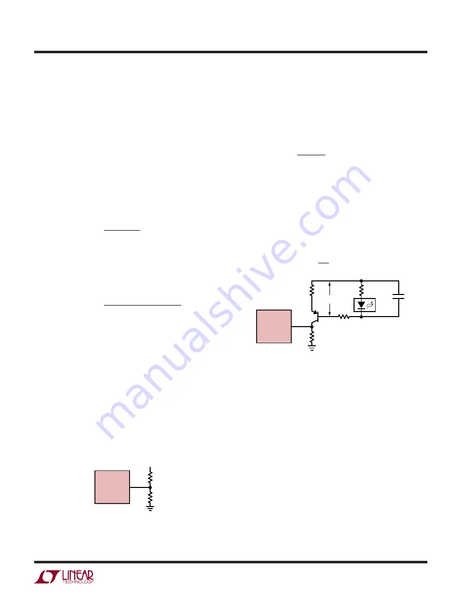
FB

LT3956

100k

V

OUT

C

OUT

R4

3956 F03

R3

LED

ARRAY

R

LED

+

Figure 3. Feedback Resistor Connection for 

Buck Mode or Buck-Boost Mode LED Driver

Programming Output Voltage (Constant-Voltage 

Regulation) or Open LED/Overvoltage Threshold 

For a boost or SEPIC application, the output voltage can 

be set by selecting the values of R3 and R4 (see Figure 2) 

according to the following equation:


V

R

R

R

OUT

=

+

1 25

3

4

4

. •

For a boost type LED driver, set the resistor from the output 

to the FB pin such that the expected voltage level during 

normal operation will not exceed 1.1V. For an LED driver 

of buck mode or a buck-boost mode configuration, the 

output voltage is typically level-shifted to a signal with 

respect to GND as illustrated in Figure 3. The output can 

be expressed as: 


V

V

R
R

OUT

BE

=

+

1 25

3
4

. •

ISP/ISN Short-Circuit Protection Feature for SEPIC

The ISP and ISN pins have a protection feature indepen-

dent of the LED current sense feature that operates at 

ISN below 3V. The purpose of this feature is to provide 

continuous current sensing when ISN is below the LED 

current sense common mode range (during start-up or 

an output short-circuit fault) to prevent the development 

of excessive switching currents that could damage the 

power  components  in  a  SEPIC  converter.  The  action 

threshold (335mV, typ) is above the default LED current 

sense threshold, so that no interference will occur over 

the ISN voltage range where these two functions overlap. 

This feature acts in the same manner as switch-current 

limit — it prevents switch turn-on until the ISP/ISN differ-

ence falls below the threshold.

Содержание LT3956 Series

Страница 1: ...imming capability 94 Efficient 25W White LED Headlamp Driver n 3000 1 True Color PWMTM Dimming n Wide Input Voltage Range 4 5V to 80V n Output Voltage Up to 80V n Internal 3 3A 84V Switch n Constant C...

Страница 2: ...ww linear com leadfree This product is only offered in trays For more information go to http www linear com packaging PARAMETER CONDITIONS MIN TYP MAX UNITS VIN Minimum Operating Voltage VIN Tied to I...

Страница 3: ...se Amplifier Input Common Mode Range VISN 2 9 80 V ISP ISN Short Circuit Threshold V ISP ISN ISN 0V 300 335 370 mV ISP ISN Short Circuit Fault Sensing Common Mode Range VISN 0 3 V ISP ISN Input Bias C...

Страница 4: ...m Ratings may cause permanent damage to the device Exposure to any Absolute Maximum Rating condition for extended periods may affect device reliability and lifetime Note 2 The LT3956E is guaranteed to...

Страница 5: ...125 1 96 1 98 2 00 2 02 2 04 1 97 1 99 2 01 2 03 VIN V 1 96 V REF V 1 98 2 00 2 02 2 04 1 97 1 99 2 01 2 03 3956 G06 0 20 40 80 60 3956 G08 SWITCHING FREQUENCY kHz TEMPERATURE C 50 0 50 75 25 25 100 1...

Страница 6: ...SWITCHING 3956 G15 INTV CC V TEMPERATURE C 50 0 50 75 25 25 100 125 7 0 7 2 7 4 7 1 7 3 DUTY CYCLE 2 5 SW PIN CURRENT LIMIT A 3 5 4 5 3 0 4 0 3956 G16 0 25 50 75 100 FB VOLTAGE V 3956 G17 1 2 1 22 1 2...

Страница 7: ...ons from a linear function to a constant value reaching 98 of full scale value by VCTRL 1 1V Connect CTRL to VREF for the 250mV default threshold Do not leave this pin open NC NoInternalConnection The...

Страница 8: ...or If not used connect to INTVCC VMODE An open collector pull down on VMODE asserts if the FB input is greater than the FB regulation threshold minus 50mV typical To function the pin requires an exter...

Страница 9: ...llowed to exceed the current limit threshold of 3 9A typical If the SW pin exceeds the current limit threshold the SR latch is reset regardless of the output state of the PWM compara tor Likewise at a...

Страница 10: ...t Programming The LED current is programmed by placing an appropri ate value current sense resistor RLED between the ISP and ISN pins Typically sensing of the current should be done at the top of the...

Страница 11: ...T R4 3956 F03 R3 LED ARRAY RLED Figure 3 Feedback Resistor Connection for Buck Mode or Buck Boost Mode LED Driver Programming Output Voltage Constant Voltage Regulation or Open LED Overvoltage Thresho...

Страница 12: ...alue see Table 1 An external resistor from the RT pin to GND is required do not leave this pin open Table 1 Switching Frequency vs RT Value fOSC kHz RT k 1000 10 900 11 8 800 13 700 15 4 600 17 8 500...

Страница 13: ...to have occurred Input Capacitor Selection Theinputcapacitorsuppliesthetransientinputcurrentfor the power inductor of the converter and must be placed andsizedaccordingtothetransientcurrentrequirement...

Страница 14: ...ent Duringstart upwithEN UVLO charging of the soft start capacitor is enabled after the first PWM high period Schottky Rectifier Selection The power Schottky diode conducts current during the interval...

Страница 15: ...ane under the switching node to eliminate interplane coupling to sensitive signals The lengths of the high dI dt traces 1 from the switch node through the switch to PGND and 2 from the switch node thr...

Страница 16: ...F s 5 CC 4 7nF VIN 6V TO 60V 80V TRANSIENT CSS 47nF R2 100k RC 20k RT 28 7k 375kHz CVCC 4 7 F 40 2k CTRL R4 16 2k R3 1M RS 0 68 370mA M1 INTVCC 3956 TA02a VMODE PWM SS RT ISN FB PWMOUT M1 VISHAY SILI...

Страница 17: ...iency vs VIN VIN V 0 10 80 EFFICIENCY 84 88 92 96 100 30 40 3956 TA03b 20 50 28VIN 0V to 28V SEPIC SuperCap Charger with Input Current Limit VIN LT3956 L1A 33 H 1 1 GND VC INTVCC INTVCC EN UVLO SW VRE...

Страница 18: ...0 EFFICIENCY 84 88 92 96 100 30 40 3956 TA05b 20 50 Typical Applications Efficiency vs VIN 90W Buck Mode LED Driver 80VIN 60VOUT VIN VIN LT3956 GND VC INTVCC VREF INTVCC EN UVLO SW ISP 100k INTVCC 1M...

Страница 19: ...CE FOR PIN 1 LOCATION ON THE TOP AND BOTTOM OF PACKAGE PIN 1 TOP MARK NOTE 6 0 40 p 0 10 1 36 35 30 31 32 33 34 28 20 21 23 24 25 27 2 3 4 6 8 9 10 12 13 14 15 16 17 BOTTOM VIEW EXPOSED PAD 2 00 REF 1...

Страница 20: ...n LED Driver VIN 4V to 36V VOUT MAX 13 5V True Color PWM Dimming 3000 1 ISD 1 A TSSOP20E Package LT3476 Quad Output 1 5A 36V 2MHz High Current LED Driver with 1000 1 Dimming VIN 2 8V to 16V VOUT MAX 3...

Отзывы: