5
dc2518af
DEMO MANUAL DC2518A
QUICK START PROCEDURE
The following procedure describes how to set up a DC2518A
demo system.
1. Download and install the LTpowerPlay GUI:
2. Remove the board from the ESD protective bag and
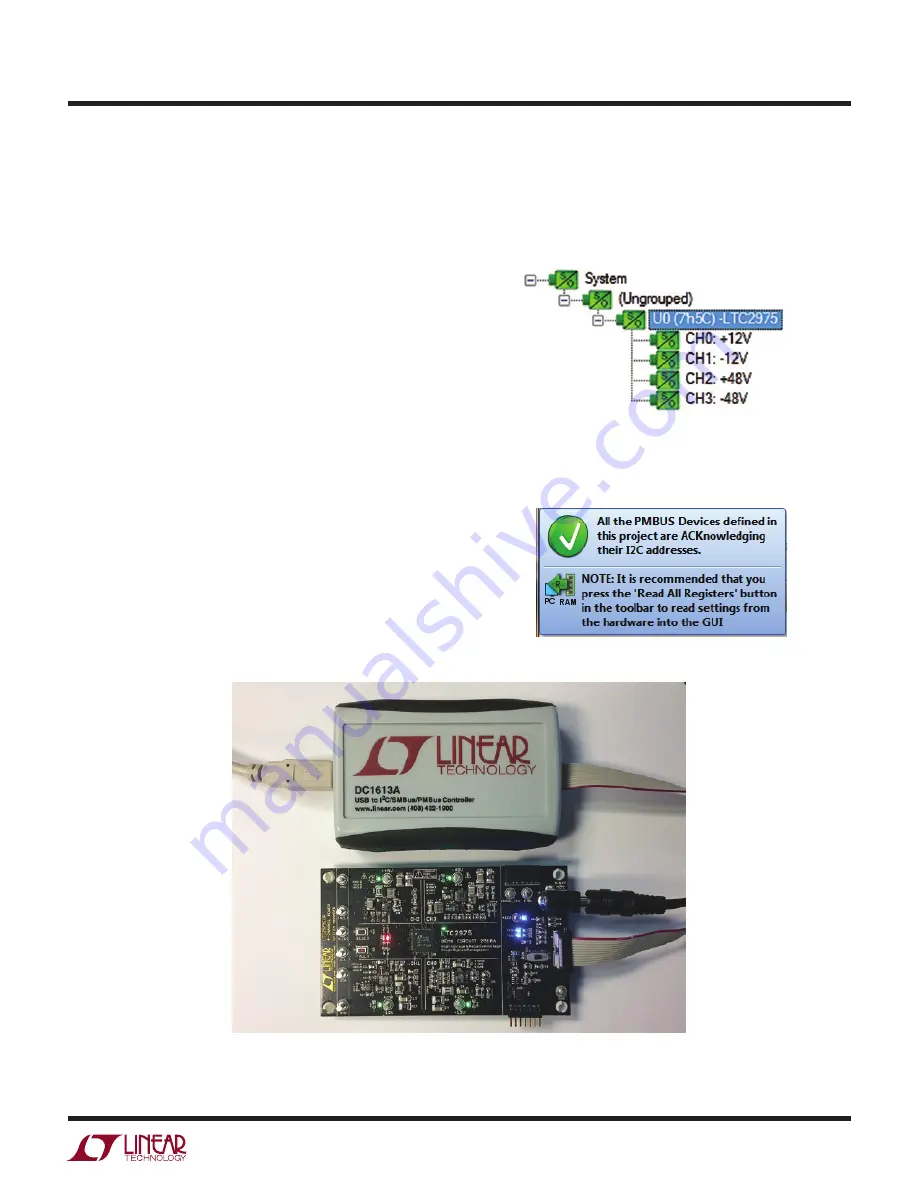
place it on a level surface. Connect the DC1613 I
2
C/
SMBus/PMBus controller to the DC2518A board using
the 12-pin ribbon cable.
3. Confirm that the RUN switch is set to its OFF position.
4. Plug the DC1613 USB-to-I
2
C/SMBus/PMBus controller
into a USB port on your PC. The board should power up
with the LED labeled “LTC2975 ON” illuminated green.
5. Connect a +12VDC power supply with > 1A capacity to
the V
IN
input jack of the DC2518A board. The blue LEDs
will illuminate indicating that DC jack power and input
power to the LDOs is applied. Move the RUN switch to
the ON position. The four outputs will power up and
the green LEDs will illuminate.
6. Launch the LTpowerPlay GUI.
a. The GUI automatically identifies the DC2518A and
builds a system tree for each I
2
C device. The system
tree on the left hand side will look like this:
Figure 3. Connecting DC2518A and the DC1613 USB to I
2
C/SMBus/PMBus Controller
b. A green message box will be displayed momentarily
in the lower left hand corner confirming that the
DC2518A is communicating.


