14
dc2518af
DEMO MANUAL DC2518A
slope. Energy is still being accumulating but at a lower
rate since channels 0 and 1 remain enabled. Note that the
input current changed from about 130mA down to 0mA
as seen in the READ_IIN register. The MFR_EIN_WATTS
register displays the input power that is being drawn. This
register is the product of the READ_VIN and READ_IIN
values. Since the input voltage is 12V, the input power is
12V • 130mA or 1.56W. You can confirm this by clicking
these three registers one by one and view the telemetry
window.
The MFR_EIN and MFR_EIN_TIME registers may be reset
by right-clicking the MFR_EIN register which displays an
option menu to “Clear HW Register”. It may also be reset
by writing the MFR_EIN_CONFIG register.
Output Voltage Sensing Schemes
The voltage sensing schemes employed on the DC2518A
are of three types. For positive voltage channels (CH0 and
CH2), a voltage divider performs this function in a simple
manner. It’s inexpensive, takes up little board space, but
introduces error in the voltage reading. For negative voltage
channels (CH1 and CH3), two different sensing methods
are used. One method uses a divider that is referenced
to the REFP pin while the other method uses an op-amp
that converts the sensed voltage to a positive single-ended
divided-down voltage.
For the positive high voltage rails, a simple divider is
used. The equation that relates divider resistors and the
rail voltage is as follows:
V
SNSP
= V
RAIL
•
R
BOT
R
TOP
+ R
BOT
+ I
SNSP
•
R
TOP
||R
BOT
The primary source of error is due to resistor tolerance.
This is the reason 0.1% resistors are used. A secondary
source of error comes from the I
SENSEP
pin current that
is pulled from the divider into the LTC2975. The divider’s
IR drop is due to the product of the Thevenin equivalent
resistance and the I
SENSEP
current. To minimize this error,
the Thevenin resistance should be less than 2k.
ADVANCED DEMO BOARD OPERATIONS
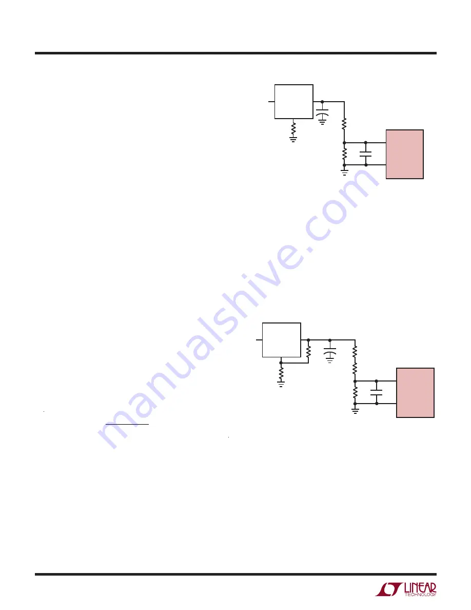
Figure 11. Output Voltage Sensing
The divider on CH2 (+48V) is 27k and 3k and the Thevenin
equivalent resistance is 2.727k. The top resistor is com-
prised of two series resistors in order to keep the power
dissipation within the limits of the 0603 case size which
a 100mW rating. The divided voltage is 4.8V, and the pin
current is 9μA. This information can be found in the Typical
Operating Characteristics curve of the LTC2975 data sheet.
The IR drop is ~24mV. This introduces approximately 0.5%
error in the sensed voltage.
+
LT3081
V
IN
V
OUT
R
SET
240k
+15V
+12V
C3
10μF
R
TOP
2k
+4V
C1
10nF
DIVIDE-BY-3
R
BOT
1k
SET
DC2518A F11
LTC2975
V
SENSEP
V
SENSEM
Figure 12. High Voltage Sensing
+
LT8330
V
IN
V
OUT
R5
10.7k
+12V
+48V
C3
4.7μF
R1
13.7k
R2
13.3k
+4.8V
C1
10nF
DIVIDE-BY-10
R3
3.01k
FBX
DC2518A F12
LTC2975
V
SENSEP
V
SENSEM
R4
309k
For the –12V channel (CH1), a divider is used; however,
the V
SENSE
pins must be kept above GND. To accomplish
this, the V
SENSEP
pin is tied to a positive voltage and the
V
SENSEM
pin to the divider. This arrangement not only
divides the rail voltage down to a safe level but also pro-
vides an absolute value of the divided voltage. There are
three sources of error in this case: the positive reference
voltage that the top of the divider is connected to, the
resistor tolerances, and the V
SENSEM
pin current that is
pushed into the divider node.


