2
dc1513bf
DEMO MANUAL DC1513B
QUICK START PROCEDURE
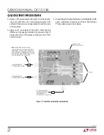
Figure 1. Proper Measurement Equipment Setup
3. Apply an RF input signal to the board. For best results,
use a low distortion, low noise signal generator with
sufficient filtering to avoid degrading the performance
of the receiver.
4. Apply an LO input signal to the board. Note that the
difference in frequency between this signal and the RF
signal will be the IF frequency resulting at the IF filter
and ADC input.
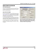
5. Observe the ADC output with demo circuit DC890B, a USB
cable, a Windows computer, and Linear Technology’s
PScope data processing software.
POWER SUPPLY
(5V AT 0.5A, 3V AT 1A)
TO DC890
RF SIGNAL GENERATOR
(HP 8644B) OR OTHER
LOW PHASE NOISE
CLOCK SOURCE (e.g. DC1216)
NOTE:
EVEN A HIGH QUALITY SIGNAL
SYNTHESIZER WILL STILL HAVE NOISE AND
HARMONICS THAT SHOULD BE ATTENUATED
WITH A LOWPASS OR BANDPASS FILTER. FOR
GOOD QUALITY HIGH ORDER FILTERS, SEE TTE,
LARK ENGINEERING, OR EQUIVALENT.
SIGNAL GENERATOR
HP 8644B OR EQUIVALENT
BPF
BPF
SIGNAL GENERATOR
HP 8644B OR EQUIVALENT
BPF


