background image

English 

Manual 


5


© LINDY ELECTRONICS LIMITED & LINDY-ELEKTRONIK GMBH  -  FIRST EDITION (DEC 2001) 


Installation 


BEFORE YOU BEGIN 


1. Make sure that power to all the devices you will be connecting up have 
been turned off. You must unplug the power cords of any computers that 
have the Keyboard Power On function. Otherwise, the switch will receive 
power from the computer. 
2. To prevent damage to your equipment due to ground potential difference, 
make sure that all devices on the installation are properly grounded. 
Consult your dealer for technical details, if necessary. 


Single Stage Installation 


For an installation without cascading please use the following steps: 

1.  Connect the console cables to keyboard, mouse, monitor, speakers and microphone. 

2.  Connect the PCs with the appropriate PC ports of the CPU Switch. Use the appropriate LINDY 

systems cables as described before in chapter CABLES.  

3.  Connect the enclosed power supply to the mains and plug in its DC power cable to the CPU 

Switch.  

4.  Switch on the CPU Switch.  

The Switch now undergoes a short Power-On-Self-Test. If there is a problem the LEDs will flash 
according to one of the following patterns: 


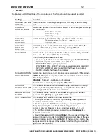
LED Lighting Pattern 


Indication 

ONLINE LEDs 1-8 flash simultaneously 

Internal RAM memory error 

ONLINE LEDs 1-8 flash one after the other 

External RAM memory error 

ONLINE LEDs 1-8 pairs flash: 1+2, then 3+4, then 
5+6, then 7 + 8, one after the other pair. 

ROM Test error 


If any of these occur turn off the switch and then turn on again. If this does not help please 
detach all cables from the rear side of the CPU Switch and turn off and switch on again. If the 
error still is present please contact the LINDY support hotline or your local dealer.  
 

5.  Complete all cable connections to the PCs that shall be connected. 

6.  Switch on all the PCs only after this procedure is complete. 


Содержание 2X8

Страница 1: ...LINDY ELECTRONICS LIMITED LINDY ELEKTRONIK GMBH FIRST EDITION DEC 2001 CPU Switch MultiMedia 2X8 Manual English Benutzerhandbuch Deutsch 2 User 8 PC LINDY Art Nr 32812 4 User 8 PC LINDY Art Nr 32814...

Страница 2: ...ad this manual thoroughly and follow the installation and operation procedures carefully to prevent any damage to the LINDY CPU Switch unit and or any of the devices connected to it We have tried to k...

Страница 3: ...ate all machines from your regular desk The switching between the connected PCs servers is easily done by selecting the PCs from the On Screen Display OSD of the CPU Switch All PCs are displayed arran...

Страница 4: ...used with this CPU Switch The first two consoles are connected via standard connection cables for SVGA PS 2 and Audio Stereo with 3 5mm Stereo connectors but also LINDY KVM cables including SVGA and...

Страница 5: ...nd need to be reset carefully insert a pointed object in here and push 5 Power LED Lights blue to indicate that the LINDY CPU Switch MultiMedia is turned on and receiving power 1 Power switch ON OFF 2...

Страница 6: ...appropriate LINDY systems cables as described before in chapter CABLES 3 Connect the enclosed power supply to the mains and plug in its DC power cable to the CPU Switch 4 Switch on the CPU Switch The...

Страница 7: ...ends the access 2 Solution for fully simultaneous access for a certain amount of servers Users are connected to the CPU Switch LITE series switches LITE OSD 8 or LITE 2 or LITE 4 Multiple CPU Switch M...

Страница 8: ...te installation please follow the following steps First power down all PCs or downstream cascaded CPU switches and PCs connected to the CPU switch you want to power down Then power down the CPU Switch...

Страница 9: ...nnected and powered up with a symbol like a sun NAME If a name was given it will be showed here For security purpose the OSD also includes a multi level password protection for up to 4 users and one a...

Страница 10: ...first user is disconnected see F5 ADM Set Access Timeout Also if cascaded no input to this port is possible AND the screen stays dark OSD Display window of selected port server The OSD can show the s...

Страница 11: ...g and changing of the information displayed in the OSD and the auto scan settings Choice Meaning ALL Lists all Ports and servers with their name QVIEW Lists only the ports having been selected for aut...

Страница 12: ...means that the port will be permanently blocked for all other users CLEAR THE NAME LIST This function is used to undo all Administrator changes and return to the original factory default settings Not...

Страница 13: ...at have been named SCAN DURATION Selects the dwell time per port in auto scan selectable 1 255 seconds PRIVATE MODE ENABLE This port computer can be accessed from this console only after being selecte...

Страница 14: ...ue 2 If you re enter the OSD after logging out and immediately use Esc to deactivate the OSD without having selected a port from the OSD menu a Null Port message displays on the screen and the system...

Страница 15: ...socket VGA SVGA Console ports 1 2 Audio 2 consoles with 2 x 3 5mm stereo socket Console ports 3 4 Version 4x8 only 2 consoles with system cable for monitor mouse keyboard speaker and microphone PC por...

Страница 16: ...hat the EMC compatibility is not badly influenced FCC Statement This device complies with Part 15 of the FCC Rules Operation is subject to the following two conditions 1 this device may not cause harm...

Страница 17: ...e die hilfreichen Installations und Bedienhinweise um Besch digungen des CPU Switch oder der angeschlossenen Rechner zu vermeiden Wir haben uns M he gegeben es so kurz und knapp wie m glich aber trotz...

Страница 18: ...er sind vom gewohnten Arbeitsplatz mit allen lokalen Unterlagen aus bedienbar Das Umschalten zwischen den angeschlossenen Rechnern erfolgt bequem ber die OSD Auswahl Im OSD werden alle angeschlossenen...

Страница 19: ...zielle Systemkabel verwendet siehe unten stehende Tabelle Prinzipiell werden die ersten beiden Arbeitspl tze mit SVGA Kabel Monitor und PS 2 Kabel Tastatur und Maus sowie Audio Stereo Kabel angeschlos...

Страница 20: ...oder einen Kugelschreiber um diesen versenkten Taster zu bet tigen dies l st einen Warmstart des CPU Switch aus Wird die Taste l nger als 3 Sekunden gehalten so l st dies einen Kaltstart aus 5 Power...

Страница 21: ...eine Steckdose und verbinden Sie anschlie end das Niederspannungskabel mit der Buchse f r die Stromversorgung am CPU Switch 4 Schalten Sie den CPU Switch ein Der Switch f hrt nun einen Power On Selbs...

Страница 22: ...n einer komplexen Matrix mit Voll Simultanzugriff f r 4 User gesteuert werden Hierf r werden ben tigt 4 LINDY CPU Switch MultiMedia 4x8 sowie 4 weitere Einzel User CPU Switch mit mindestens 4 Ausgangs...

Страница 23: ...lte einen Ihrer LINDY CPU Switches auszuschalten m ssen Sie wie folgt vorgehen Fahren Sie alle Rechner die mit dem Ger t verbunden sind sowie alle auf niedrigeren Ebenen kaskadierten CPU Switches und...

Страница 24: ...ie angeschlossen eingeschaltet und On line sind mit einem sonnigen Symbol NAME Wenn f r einen Anschluss ein Name vergeben wurde wird dieser hier angezeigt F r Sicherheitsbelange wird ber das OSD ferne...

Страница 25: ...gaben auf diesem Rechner m glich Dies gilt analog auch f r kaskadierte Ports allerdings bleibt der bildschirm dunkel Anzeige des ausgew hlten Rechners Das OSD des CPU Switch erlaubt die Anzeige des au...

Страница 26: ...ung ALL Listet alle CPU Switch Ports mit Namen QVIEW Listet nur die Anschl sse die f r den Zugriff im Quick View Scan Modus selektiert wurden POWERED ON Listet nur die Anschl sse an denen die angeschl...

Страница 27: ...nach der letzen Eingabe Maus oder Tastaur Der Wert 0 beduetet hier dass der Rechner nicht freigegeben wird bis der Benutzer auf einen anderen Rechner umschaltet CLEAR THE NAME LIST Setzt ALLE Einstel...

Страница 28: ...kierung des OSD Eintrag QV POWERED ON alle eingeschalteten POWERED ON QVIEW alle eingeschalteten mit Eintag QV QVIEW NAME alle mit Eintrag QV und mit Namen NAME nur die die einen Namen haben SCAN DURA...

Страница 29: ...Keine Funktion von Tastatur und oder Maus Versuchen Sie zuerst durch Umschalten und Zur ckschalten wieder Zugriff auf den Rechner zu erlangen Pr fen Sie ob die zum Port Rechner zugeh rige ONLINE LED a...

Страница 30: ...Konsolen mit HD 15 Buchse VGA SVGA Konsolen anschl sse 1 2 Audio 2 Konsolen mit 2x 3 5mm Stereo Buchse Konsolen anschl sse 3 4 Nur bei Version 4x8 2 Konsolen mit Systemkabel f r Monitor Maus Tastatur...

Страница 31: ...eferten Netzteil betrieben werden Nur in diesem Fall kann von der Einhaltung der EMV Kompatibilit t ausgegangen werden vorausgesetzt alle im System integrierten Komponenten erf llen ebenfalls ihrersei...

Страница 32: ...ELEKTRONIK GMBH FIRST EDITION DEC 2001 English Manual Deutsches Benutzerhandbuch LINDY CPU Switch MultiMedia Models 2X8 and 4X8 Full Audio Support Simultaneous Multi User 2 User 8 PC LINDY Art Nr 3281...

Отзывы: