background image

8

/17

The implementation of a periodic inspection plan allows to guaran-

tee the efficiency and functionality of the fire dampers for the fire 

safety of the building.


„

Periodic inspection and cleaning

Periodic inspection shall be performed in accordance with the re-

quirements of the law or by the building regulations or other local 

regulations.

In the absence of specific regulations (or to their complement), in ac-

cordance with point 8.3 of the EN 1560 standard, it is recommended 

to carry out the following control activities at intervals of no more 

than 6 months:

•  If the damper is connected to a remote control or command sys-

tem (eg BMS or alarm or fire detection), that responds correctly to 

commands by performing at least one opening and closing test 

and verifying the correct movement of the blade and the correct 

functioning of the microswitches (limit switches).

•  If the damper is not connected to a remote control or command 

system, manually execute an opening and closing test and check 

the correct movement of the blade and the correct functioning of 

the microswitches (limit switches) if present.

Together with the control activities, it is recommended to visually 

verify the absence of corrosion, the integrity of the electrical wiring 

and the sealing of the construction support.

Damper cleaning is included in the ordinary maintenance activities 

of the ventilation ducts.

Fire dampers can be cleaned with a dry or wet cloth.

In the case of resistant dirt, it is possible to use normal household 

detergents.

If prescribed for the type of building, it is possible to use disinfectant 

detergents.

The use of detergents or mechanical abrasive cleaning systems is not 

permitted.

These indications comply with the standards EN 15650 annex D and 

EN 15423 annex C.


„

Repair

For safety reasons, repair activities involving fire-fighting compo-

nents must be carried out only by qualified personnel.

Only original spare parts supplied by the fire damper manufacturer 

must be used.

A functional test must be performed after each repair.

.

At the end of the inspection, cleaning or repair operations, check that 

the fire damper is in the normal operating position.

Keep records of all inspections, repair activities, any problems en-

countered and their resolution.

This practice, even when not mandatory, is very useful in practice.


„

Disposal

Disposal in case of destruction must be carried out in accordance 

with national legislation. For electrical and electronic parts also refer 

to EU Directive 2011/65.

INSTALLATION

The sizes shown are in mm.

It is recommended to perform a functional test before Installation to 

exclude possible damage during transport and another test immedi-

ately after installation to exclude accidental damage to the product 

and interference with mounting components.


„

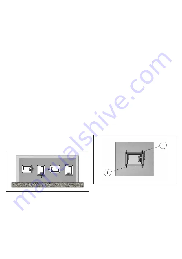
Blade rotation axis positioning

The fire damper can be installed both with the blade axis positioned 

vertically or horizontally.


„

Positioning brackets before fixing

1.  WKGY100 fixing brackets (accessory to order separately, one size valid for all 

fire dampers kind)

WKGY100 fixing brackets are obligatory for intallations within plaster-

board walls and suggested for walls with 100 mm thickness.

They are not usable for installations with Fire Batt (Weichschott) seal-

ing.


„

Installation of flexible connectors in order to balance out the 

ventilation ducts expansion

CAUTION: Refer anyway to law and national standardization.

Flexible connectors compensate any duct thermal expansion and 

wall bending in case of fire.

Flexible connectors are used to limit fire damper stresses due to ex-

ternal forces in case of fire and to preserve fire resistance class.

In general it is always appropriate the use of flexible connectors for 

the followings installations:

– light walls;

– Plasterboard and rock wool or Fire Batt (Weichschott) sealing;

– Applique fixing system.

Содержание WK45 Series

Страница 1: ...data the equipment and acces sories indicated could be subject to variations Installation booklet RECTANGULAR SERIES WK45 500 Pa 300 Pa Cert N 1812 CPR 1006 EN 15650 This is a 17 page installation bo...

Страница 2: ...ling ve i o D B X H min 200 X 200 max 1500 X 800 B X H min 200 X 200 max 1500 X 800 B X H min 200 X 200 max 1500 X 800 EI 120 S Installation within vertical light wall gypsum blocks wall Wall minimum...

Страница 3: ...sealing Wall minimum thickness 100 mm Wall minimum density 995 kg m Rock wool 140 kg m and endothermic varnish sealing ve i o W B X H min 200 X 200 max 1500 X 800 B X H min 200 X 200 max 1500 X 800 B...

Страница 4: ...r In case of closed damper as a result of the action of the thermosen sitive element it is possible to manually reopen the damper by rotat ing the lever counterclockwise once the element has been repl...

Страница 5: ...sing by remote control If power to the motor is cut off the blade will close Temperature calibration of thermosensitive element for auto matic damper closing 72 C 7 C Standard 95 C 9 C On request Fire...

Страница 6: ...roswitch When the fire blade is closed the circuit is closed 3 NC contact of SA microswitch When the fire blade is open the circuit is open 4 NO contact of SA microswitch When the fire blade is open t...

Страница 7: ...24V DC or 230 V AC version Motor 24V AC DC WK45VMB Belimo BFN24T Opening 4 W In stand by 1 4 W Motor 230V AC WK45DMB Belimo BFN230T Opening 5 W In stand by 2 1 W Motor 24V AC DC WK45VGB Belimo BF24T O...

Страница 8: ...volving fire fighting compo nents must be carried out only by qualified personnel Only original spare parts supplied by the fire damper manufacturer must be used A functional test must be performed af...

Страница 9: ...ntion fire resistance classification for transfer application is conform to section Fire resistance classification according to EN 13501 3 2009 limited to EI 120S if the ducted classification is high...

Страница 10: ...k wool 100 kg m sealing 70 75 Yes One air duct Flexible wall EI 120 S Installation within vertical light wall plasterboard Mortar or plaster putty sealing 70 75 Yes Separate air duct EI 90 S Installat...

Страница 11: ...ls floor of the same type but with greater thickness and or densi ty than those used in the test For plasterboard walls the test results are also valid for walls with a greater number of plasterboard...

Страница 12: ...haped edges as indicated in the supplier s instruc tions and according to the following characteristics minimum thickness 70 or 100 mm according to the type and re sistance class required minimum dens...

Страница 13: ...bove D2 Hole height see table above E Damper protrusion from the wall see table above Installations within vertical light wall plasterboard Refer to the section Construction supports characteristics f...

Страница 14: ...provided in the wall as indicated in the table and in the drawing Damper positioning Position the damper in the opening so that the side of the closing mechanism extends as indicated in the table and...

Страница 15: ...damper H Nominal height of the damper D1 Hole base see table above D2 Hole height see table above E Damper protrusion from the floor see table above S Floor minimum thickness see table above 1 Mortar...

Страница 16: ...sealant 3 PROMASTOP E PASTE or HILTI CFS CT endothermic varnish Installation within floor with Fire Batt Weichschott sealing Refer to the section for further information Comply with the minimum dista...

Страница 17: ...Hole height see table above E Damper protrusion from the floor see table above 1 Rock wool panel 50 mm thick with 140 kg m density 2 PROMASTOP E PASTE or HILTI CFS S ACR type sealant 3 PROMASTOP E PAS...

Отзывы: