


6.4 Hydraulic connections
The lubrication line should be connected to the central unit so that no
force can be transmitted to the unit once installed (no pressure on
the connection).
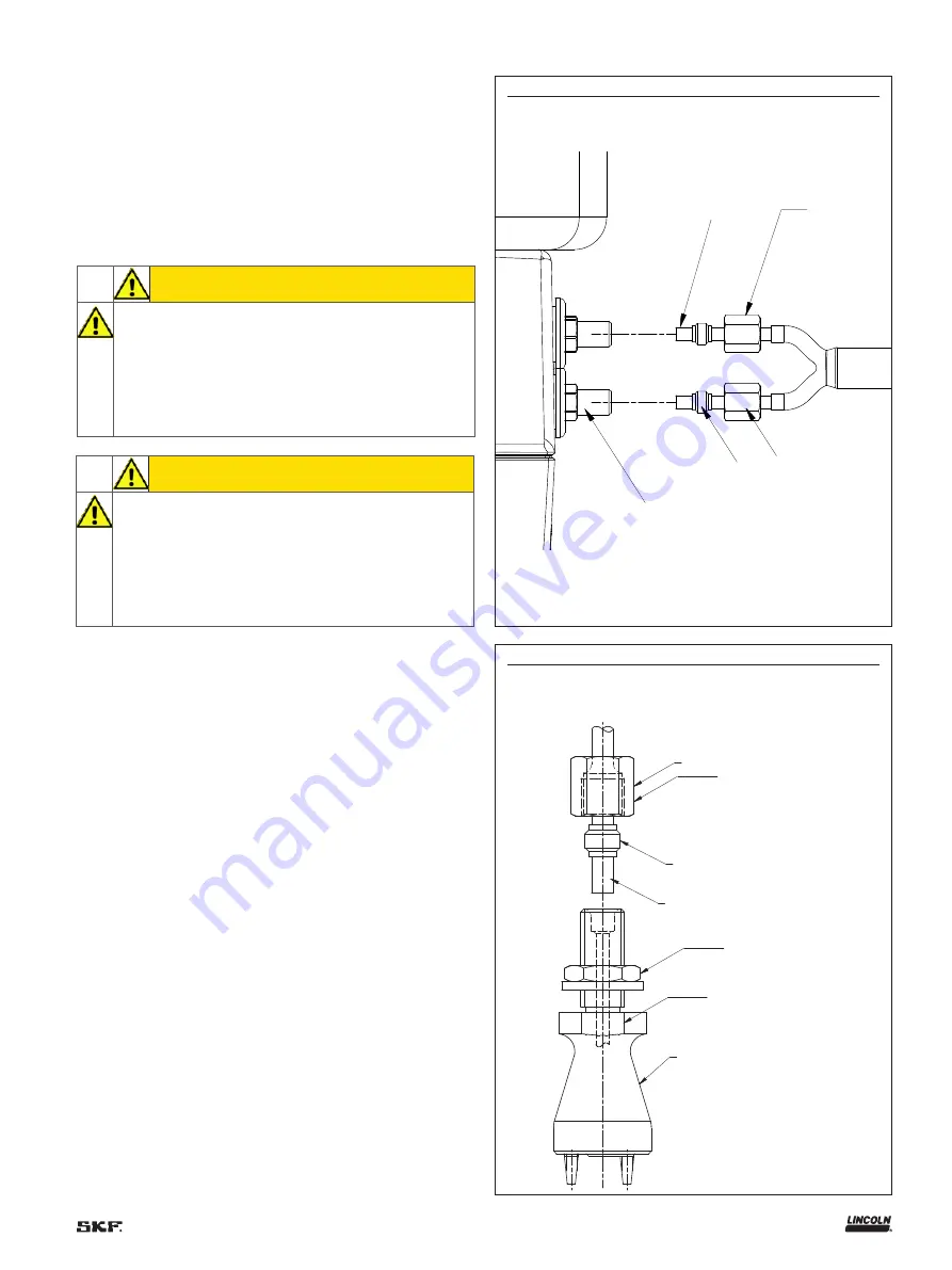
6.4.1 Central unit outputs
The central unit is equipped with two to four lubricant outputs
depending on the model. These outputs are located on the housing
side. The connection is made by crimp ring fittings for stainless steel
pipes with an outer diameter of 4 mm
(† fig. 13)
.
6.4.2 Nozzles
The nozzle connection
(† fig. 14)
is made by crimp ring fittings for
stainless steel pipes an with outer diameter of 4 mm
CAUTION
The connectors and accessories used to connect the lubri-
cant line must be compatible with the pump's maximum
service pressure.
CAUTION
The line maximum length between the central unit and the
projection nozzles is 5 m. For a higher length, contact the
SKF Service Center.
SW10
1
2
3
4
Fig. 13
Central unit output connection
1
2
4
SW 10
SW 12
SW 14
3
Fig. 14
Nozzle connection
1
Stainless steel pipe Ø 4 mm
2
Central unit output
3
Double tapered sleeve
4
Union nut
1
M8×1
2
Double tapered sleeve
3
Pipe outer Ø 4 mm
4
Projection nozzle
21
Содержание SKF CLK
Страница 37: ...37 ...


