


Accessories
. . . . . . . . . . . . . . . . . . . . . . . . . . . . . . . . . . . . . . . . . . . . . . . . . . . . . . . . . . . . . . . . . . . .Section C
Optional Field Installed Accessories . . . . . . . . . . . . . . . . . . . . . . . . . . . . . . . . . . . . . . . . . . . . . . . . . .C-1
Maintenance
. . . . . . . . . . . . . . . . . . . . . . . . . . . . . . . . . . . . . . . . . . . . . . . . . . . . . . . . . . . . . . . . . . . .Section D
Safety Precautions . . . . . . . . . . . . . . . . . . . . . . . . . . . . . . . . . . . . . . . . . . . . . . . . . . . . . . . . . . . . . . .D-1
Routine and Periodic Maintenance . . . . . . . . . . . . . . . . . . . . . . . . . . . . . . . . . . . . . . . . . . . . . . . . . . .D-1
Engine Maintenance . . . . . . . . . . . . . . . . . . . . . . . . . . . . . . . . . . . . . . . . . . . . . . . . . . . . . . . . . . . . . .D-1
Air Filter . . . . . . . . . . . . . . . . . . . . . . . . . . . . . . . . . . . . . . . . . . . . . . . . . . . . . . . . . . . . . . . .D-1
Fuel Filters . . . . . . . . . . . . . . . . . . . . . . . . . . . . . . . . . . . . . . . . . . . . . . . . . . . . . . . . . . . . . .D-2
Fuel Pre-Filter/Water Separator Assembly . . . . . . . . . . . . . . . . . . . . . . . . . . . . . . . . . . . . . .D-2
Water Separator . . . . . . . . . . . . . . . . . . . . . . . . . . . . . . . . . . . . . . . . . . . . . . . . . . . . . . . . . .D-2
Secondary Fuel Filter . . . . . . . . . . . . . . . . . . . . . . . . . . . . . . . . . . . . . . . . . . . . . . . . . . . . . .D-2
Cooling System . . . . . . . . . . . . . . . . . . . . . . . . . . . . . . . . . . . . . . . . . . . . . . . . . . . . . . . . . .D-3
Cooling Blower Belt . . . . . . . . . . . . . . . . . . . . . . . . . . . . . . . . . . . . . . . . . . . . . . . . . . . . . . .D-3
Battery Handling . . . . . . . . . . . . . . . . . . . . . . . . . . . . . . . . . . . . . . . . . . . . . . . . . . . . . . . . . .D-3
Charging the Battery . . . . . . . . . . . . . . . . . . . . . . . . . . . . . . . . . . . . . . . . . . . . . . . . . . . . . .D-4
Nameplate / Warning Decal Maintenance . . . . . . . . . . . . . . . . . . . . . . . . . . . . . . . . . . . . . . . . . . . . . .D-4
Welder / Generator Maintenance . . . . . . . . . . . . . . . . . . . . . . . . . . . . . . . . . . . . . . . . . . . . . . . . . . . .D-4
Engine Maintenance Components . . . . . . . . . . . . . . . . . . . . . . . . . . . . . . . . . . . . . . . . . . . . . . . . . . .D-4
Troubleshooting . . . . . . . . . . . . . . . . . . . . . . . . . . . . . . . . . . . . . . . . . . . . . . . . . . . . . . . . . . . . . . . . . . . .Section E
Wiring, Connection Diagrams and Dimension Print . . . . . . . . . . . . . . . . . . . . . . . . . . . . . . . . . . . . . . . .Section F
Parts Lists
. . . . . . . . . . . . . . . . . . . . . . . . . . . . . . . . . . . . . . . . . . . . . . . . . . . . . . . . . . . . . . . . . . .P-472 Series
vii
vii
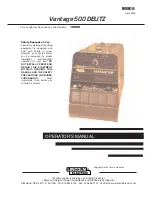
Vantage 500 DEUTZ
TABLE OF CONTENTS
Содержание Vantage 500 DEUTZ
Страница 35: ...Vantage 500 DEUTZ F 2 DIAGRAMS F 2 CONNECTION DIAGRAM ...
Страница 37: ...F 4 DIAGRAMS F 4 Vantage 500 DEUTZ CONNECTION DIAGRAM ...
Страница 38: ...Vantage 500 DEUTZ F 5 DIAGRAMS F 5 CONNECTION DIAGRAM ...
Страница 40: ...Vantage 500 DEUTZ F 7 DIAGRAMS F 7 CONNECTION DIAGRAM ...
Страница 41: ...Vantage 500 DEUTZ F 8 DIAGRAMS F 8 CONNECTION DIAGRAM ...
Страница 43: ...Vantage 500 DEUTZ F 10 DIAGRAMS F 10 CONNECTION DIAGRAM ...
Страница 44: ...Vantage 500 DEUTZ F 11 DIAGRAMS F 11 CONNECTION DIAGRAM ...
Страница 45: ...Vantage 500 DEUTZ F 12 DIAGRAMS F 12 CONNECTION DIAGRAM ...
Страница 46: ...Vantage 500 DEUTZ F 13 DIAGRAMS F 13 CONNECTION DIAGRAM ...
Страница 48: ...NOTES VANTAGE 500 DEUTZ ...