

WELDING AND CUTTING
SPARKS CAN CAUSE
FIRE OR EXPLOSION.
6.a. Remove fire hazards from the welding area. If
this is not possible, cover them to prevent the
welding sparks from starting a fire. Remember that welding
sparks and hot materials from welding can easily go through
small cracks and openings to adjacent areas. Avoid welding near
hydraulic lines. Have a fire extinguisher readily available.
6.b. Where compressed gases are to be used at the job site, special
precautions should be used to prevent hazardous situations.
Refer to “Safety in Welding and Cutting” (ANSI Standard Z49.1)
and the operating information for the equipment being used.
6.c. When not welding, make certain no part of the electrode circuit is
touching the work or ground. Accidental contact can cause
overheating and create a fire hazard.
6.d. Do not heat, cut or weld tanks, drums or containers until the
proper steps have been taken to insure that such procedures will
not cause flammable or toxic vapors from substances inside.
They can cause an explosion even though they have been
“cleaned”. For information, purchase “Recommended Safe
Practices for the Preparation for Welding and Cutting of
Containers and Piping That Have Held Hazardous Substances”,
AWS F4.1 from the American Welding Society (see address
above).
6.e. Vent hollow castings or containers before heating, cutting or
welding. They may explode.
6.f. Sparks and spatter are thrown from the welding arc. Wear oil free
protective garments such as leather gloves, heavy shirt, cuffless
trousers, high shoes and a cap over your hair. Wear ear plugs
when welding out of position or in confined places. Always wear
safety glasses with side shields when in a welding area.
6.g. Connect the work cable to the work as close to the welding area
as practical. Work cables connected to the building framework or
other locations away from the welding area increase the
possibility of the welding current passing through lifting chains,
crane cables or other alternate circuits. This can create fire
hazards or overheat lifting chains or cables until they fail.
6.h. Also see item 1.c.
6.I. Read and follow NFPA 51B “ Standard for Fire Prevention During
Welding, Cutting and Other Hot Work”, available from NFPA, 1
Batterymarch Park, PO box 9101, Quincy, Ma 022690-9101.
6.j. Do not use a welding power source for pipe thawing.
CYLINDER MAY EXPLODE IF
DAMAGED.
7.a. Use only compressed gas cylinders containing
the correct shielding gas for the process used
and properly operating regulators designed for
the gas and pressure used. All hoses, fittings,
etc. should be suitable for the application and
maintained in good condition.
7.b. Always keep cylinders in an upright position securely chained to
an undercarriage or fixed support.
7.c. Cylinders should be located:
•
Away from areas where they may be struck or subjected
to physical damage.
•
A safe distance from arc welding or cutting operations
and any other source of heat, sparks, or flame.
7.d. Never allow the electrode, electrode holder or any other
electrically “hot” parts to touch a cylinder.
7.e. Keep your head and face away from the cylinder valve outlet
when opening the cylinder valve.
7.f. Valve protection caps should always be in place and hand tight
except when the cylinder is in use or connected for use.
7.g. Read and follow the instructions on compressed gas cylinders,
associated equipment, and CGA publication P-l, “Precautions for
Safe Handling of Compressed Gases in
Cylinders,” available
from the Compressed Gas Association 1235 Jefferson Davis
Highway, Arlington, VA 22202.
FOR ELECTRICALLY
POWERED EQUIPMENT.
8.a. Turn off input power using the disconnect
switch at the fuse box before working on the
equipment.
8.b. Install equipment in accordance with the U.S. National Electrical
Code, all local codes and the manufacturer’s recommendations.
8.c. Ground the equipment in accordance with the U.S. National
Electrical Code and the manufacturer’s recommendations.
refer to
http://www.lincolnelectric.com/safety
for additional safety information.
5
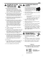
SAFETY
Welding Safety
Interactive Web Guide
for mobile devices


