


B-6
OPERATION
B-6
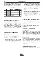
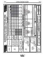
The Pro-MIG 135 is suitable for .035" aluminum wire
and .030" stainless wire. Refer to Table B.1 for recom-
mended procedure settings (requires K499 Argon
Regulator Kit).
TABLE B.1
CHANGING MACHINE OVER TO
FEED OTHER WIRE SIZES
The Pro-MIG 135 is shipped from the factory ready to
feed .023
”
-.025
”
(0.6 mm) diameter wire. To operate
the Pro-MIG 135 with other sizes of wire, it is neces-
sary to change the contact tip and change the drive
roll over to other sizes. Refer to Changing the Contact
Tip and Changing the Drive Roll, in the MAINTE-
NANCE section, for specific information on these pro-
cedures.
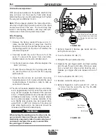
WELDING WITH GMAW (MIG)
Shielding Gas
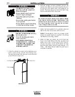
When using the GMAW process, obtain and install a
gas regulator and hose kit; K463 (for CO2) or K499
(Argon mixed) gas regulator and hose kit.
1. For CO2, open the cylinder very slowly. For argon-
mixed gas, open cylinder valve slowly a fraction of
a turn. When the cylinder pressure gauge pointer
stops moving, open the valve fully.
2. If using a regulator with an adjustable flow meter,
close the gun trigger and adjust the flow to give 15
–
20 cubic ft per hour (CFH) (7
–
10 I/min.) [use 20
–
25 CFH (10
–
12 I/min.) when welding out of
position or in a drafty location for CO2]. For argon
mixed gas, trigger to release gas pressure, and
adjust the flow to give 25
–
30 CFH (12
–
14
I/min.).
3. Keep the cylinder valve closed, except when using
the Pro-MIG 135. When finished welding:
a) Close the cylinder valve to stop gas flow.
b) Depress the gun trigger briefly to release the
pressure in the gas hose.
c) Turn off the Pro-MIG 135.
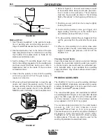
WELDING WITH FCAW (Innershield)
When using the FCAW process, the correct drive roll
and electrode polarity must be used. See Work Cable
Installation in INSTALLATION section for changing
the polarity.
Innershield welding kit K549-1 (for .035" / 0.9mm) is
also available.
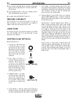
OVERLOAD PROTECTION
Output Overload
The Pro-MIG 135 is equipped with a circuit breaker
and a thermostat which protects the machine from
damage if maximum output is exceeded. The circuit
breaker button will extend out when tripped. The cir-
cuit breaker must be manually reset.
Thermal Protection
The Pro-MIG 135 has a rated output duty cycle of
20%. If the duty cycle is exceeded, a thermal protector
will shut off the output until the machine cools to a
reasonable operating temperature. This is an auto-
matic function of the Pro-MIG 135 and does not
require user intervention. The fan continues to run
during cooling.
Electronic Wire Drive Motor Protection
The Pro-MIG 135 has built-in protection for wire drive
motor overload.
Pro-MIG 135
Shielding
Voltage/Wire Speed
Process
Welding Wire
Gas
16 ga
14 ga
12 ga
10 ga
MIG DC+
.035 Dia
100% Argon
B-5
D-7
D-9
D-9
4043 Aluminum
Wire
MIG DC+
.035 Dia
100% Argon
B-5
C-7
D-9
D-10
5356 Aluminum
Wire
MIG DC+
.030 Dia
98% Argon/
A-3
C-6
D-7.5
D-7.5
308L Stainless
2% Oxygen
Steel Wire
Содержание Pro-MIG 135
Страница 31: ...B 18 APPLICATION CHART B 18 Pro MIG 135...
Страница 43: ...NOTES Pro MIG 135...
Страница 44: ...NOTES Pro MIG 135...