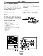
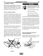
Lincoln Electric Pro-MIG 135 Скачать руководство пользователя страница 18

B-5

OPERATION

B-5

FIGURE B.6

Making A Weld

1. See 

Process Guidelines

 in this section for selec-

tion of welding wire and shielding gas and for
range of metal thicknesses that can be welded.

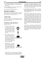
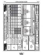
2. See the Application chart on the inside of the wire

feed compartment door for information on setting
the Pro-MIG 135 controls. Refer to Table B.1 for
aluminum and stainless wire.

3. Set the Voltage (

V

) and Wire Speed (

olo

’”

) con-

trols to the settings suggested for the welding wire
and base metal thickness being used, refer to
Applications chart on the inside of the wire drive
compartment door.

4. Check that the polarity is correct for the welding

wire being used and that the gas supply, if
required, is turned on.

5. When using Innershield electrode, remove the gas

nozzle and install the gasless nozzle. This will
improve visibility of the arc and protect the gas dif-
fuser from weld spatter. Refer to the MAINTE-
NANCE section for details on nozzle replacement.
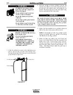
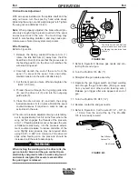
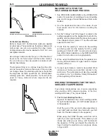
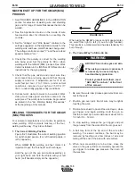
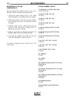
FIGURE B.7

6. Refer to Figure B.7. Connect work clamp to metal

to be welded. Work clamp must make good elec-
trical contact to the workpiece. The workpiece
must also be grounded as stated in 

Arc Welding

Safety Precautions

 in the beginning of this manu-

al.

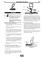
7. Position gun over joint. End of wire may be lightly

touching the work.

8. Lower welding helmet, close gun trigger, and

begin welding. Hold the gun so the contact tip to
work distance is about 3/8 inch (10 mm).

9. To stop welding, release the gun trigger and then

pull the gun away from the work after the arc goes
out.

10. When no more welding is to be done, close valve

on gas cylinder (if used), momentarily operate gun
trigger to release gas pressure, and turn off the
Pro-MIG 135.

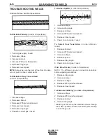
Cleaning Tip And Nozzle
Clean the contact tip and nozzle to avoid arc bridging
between the nozzle and contact tip which can result in
a shorted nozzle, poor welds and an overheated gun.
Hint: Anti-stick spray or gel, available from a welding
supply distributor, may reduce buildup and aid in spat-
ter removal.

PROCESS GUIDELINES

The Pro-MIG 135 can be used for welding mild steel
using the GMAW, single pass, process which requires
a supply of shielding gas or it can be used for the self-
shielded, Innershield

®

process (FCAW).

The recommended gases and electrodes for GMAW
are welding grade CO2 gas or an argon-CO2 blended

gas (75 to 80% argon and 25 to 20% CO2) and .025"

(0.6 mm) diameter Lincoln L-56 mild-steel welding
wire, supplied on 12-1/2 lb (5.7 kg) spools. 

The recommended electrode for the self-shielded
process is .035

 (0.9 mm) diameter Lincoln

Innershield

®

NR-211-MP on 10 lb (4.5 kg) spools.

This electrode can be used for all position welding of
20 gauge (1.0 mm) through 5/16" (8 mm) steel.
Thickness of 1/4" (6 mm) and 5/16" (8 mm) require
multiple passes. This wire can also be used for the
welding of galvanized coated sheet metal.
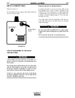
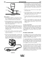
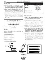
Pro-MIG 135

3/8"

 1/2" Electrical Stickout

Contact Tip

Wire Electrode

WORKPIECE

GUN CABLE

ARC

WORK CLAMP

Pro-MIG

 135

Содержание Pro-MIG 135

Страница 1: ...Code Number 10889 Pro MIG 135 Sales and Service through Subsidiaries and Distributors Worldwide Cleveland Ohio 44117 1199 U S A TEL 216 481 8100 FAX 216 486 1751 WEB SITE www lincolnelectric com World...

Страница 2: ...WEARERS SHOULD CONSULT WITH THEIR DOCTOR BEFORE OPERATING Read and understand the following safety highlights For additional safety information it is strongly recommended that you purchase a copy of...

Страница 3: ...ical earth ground 3 f Maintain the electrode holder work clamp welding cable and welding machine in good safe operating condition Replace damaged insulation 3 g Never dip the electrode in water for co...

Страница 4: ...vent the welding sparks from starting a fire Remember that welding sparks and hot materials from welding can easily go through small cracks and openings to adjacent areas Avoid welding near hydraulic...

Страница 5: ...i s et non inflamma bles 4 Des gouttes de laitier en fusion sont mises de l arc de soudage Se prot ger avec des v tements de protection libres de l huile tels que les gants en cuir chemise paisse pant...

Страница 6: ...e information must be followed to avoid minor personal injury or damage to this equipment CAUTION Please Examine Carton and Equipment For Damage Immediately When this equipment is shipped title passes...

Страница 7: ...gs B 2 Welding Operations B 3 Overload Protection B 6 Learning to Weld B 7 Application Chart B 18 Accessories Section C Accessories C 1 Replacement Parts C 2 Maintenance Section D Safety Precautions D...

Страница 8: ...L SPECIFICATIONS Pro MIG 135 INPUT SINGLE PHASE ONLY RATED OUTPUT OUTPUT RECOMMENDED INPUT CABLE AND FUSE SIZES Height Width Depth Weight 12 0 in 9 75 in 16 5 in 48 Ibs 305 mm 248 mm 419 mm 21 8 kg PH...

Страница 9: ...11 MP 7 Hand shield with filter plate and lens 8 Adjustable mixed Gas Regulator Hose 9 Instructional video 10 Gasless Nozzle For available options and accessories refer to the Accessories Section of t...

Страница 10: ...the louvers in the back and out the front of the unit A location that minimizes the amount of smoke and dirt drawn into the rear louvers reduces the chance of dirt accumulation that can block air pass...

Страница 11: ...un conductor cable through the Gun Cable Access Hole 2 in the Pro MIG 135 case front Make sure the connector is all the way in the brass connector block Unscrew thumbscrew on the connector block a few...

Страница 12: ...ith the cylinder securely installed remove the cylinder cap Stand to one side away from the out let and open the cylinder valve very slightly for an instant This blows away any dust or dirt which may...

Страница 13: ...stallation meeting applicable electrical code requirements consult a qualified electrician Requirements For Rated Output A power cord with a 15 amp 125 volt three prong plug NEMA Type 5 15P is factory...

Страница 14: ...wer and wanting the ease of use quality and dependability of both gas metal arc welding or GMAW also known as MIG welding and the Innershield electrode process self shielded flux cored or FCAW The Pro...

Страница 15: ...mode No external shielding gas is required when used with Lincoln Innershield 035 0 9 mm NR 211 MP electrode Accommodates both 4 100 mm diameter and 8 200 mm diameter spools of wire Accepts optional S...

Страница 16: ...8 200 mm diameter spool on the wire spool spindle shown in Figure B 2 To use 4 100 mm diameter spools the 2 50 mm diameter spindle must be removed See Figure B 3 Remove the wing nut and spacer at the...

Страница 17: ...idle roll pressure adjustment wing nut is factory set to approximately five full turns from where the wing nut first engages the threads of the pressure arm 1 If feeding problems occur because the wi...

Страница 18: ...ontact tip to work distance is about 3 8 inch 10 mm 9 To stop welding release the gun trigger and then pull the gun away from the work after the arc goes out 10 When no more welding is to be done clos...

Страница 19: ...the cylinder valve closed except when using the Pro MIG 135 When finished welding a Close the cylinder valve to stop gas flow b Depress the gun trigger briefly to release the pressure in the gas hose...

Страница 20: ...t current from going through an unwanted path Avoid allowing the welding circuit to pass through hinges bearings electronic components or similar devices that can be damaged See Figure B 8 Always disc...

Страница 21: ...p impurities and forms the protective slag on top of the weld during cooling After running a weld bead the slag may be removed with a chipping hammer and wire brush This improves appearance and allows...

Страница 22: ...ood that the metal is mild steel and that you will be able to weld the material In addition aluminum and stainless steel can be welded using the K664 1 Aluminum Welding Kit For further information on...

Страница 23: ...cal up or vertical down Vertical up is used whenever a larger stronger weld is desired Vertical down is used primarily on sheet metal 5 32 3 9 mm and under for fast low penetrating welds Use of this u...

Страница 24: ...to the settings suggested on the Application Guide for the welding wire and base metal thickness being used The voltage control is marked V and the wire feed speed is marked olo 4 Check that the pola...

Страница 25: ...tickout ESO is the distance from the end of the contact tip to the end of the wire See Figure B 19 Once the arc has been established maintaining the correct ESO becomes extremely important The ESO sho...

Страница 26: ...he work 2 Position face shield to protect face and eyes 3 Depress gun trigger hold gun so contact tip to work distance is about 3 8 to 1 2 inch 10 to 12 mm and the gun is at proper angle 4 After you s...

Страница 27: ...of the four welding will be easy They are as follows 1 The Correct Welding Position Figure B 23 illustrates the correct welding position for right handed people For left handed people it is the oppos...

Страница 28: ...the molten metal FIGURE B 25 Helpful Hints 1 For general welding it is not necessary to weave the arc neither forward or backward nor sideways Weld along at a steady pace You will find it easier 2 Wh...

Страница 29: ...e 2 Increase drag angle 3 Decrease stickout 4 Increase WFS wire feed speed 5 Decrease travel speed 6 Check for correct gas if used To Correct Poor Penetration in order of impor tance 1 Decrease sticko...

Страница 30: ...ll the gun around sharp corners 2 Keep the gun cable as straight as practical when welding 3 Do not allow dolly wheels or trucks to run over the cables 4 Keep the cable clean 5 Innershield electrode h...

Страница 31: ...B 18 APPLICATION CHART B 18 Pro MIG 135...

Страница 32: ...ese components due to the lubricant applied to steel wire Failure to do so may result in contaminated welds when weld ing aluminum 3 KP665 045C Drive Roll Optional Knurled drive roll for feeding 035 0...

Страница 33: ...e and thread into gun and cable per Welding Wire Loading section 1 The factory installed gun liner will feed up to 035 0 9mm wire REPLACEMENT PARTS Complete Gun and Cable Assembly L8311 6 K530 4 Conta...

Страница 34: ...roblems NO maintenance is required In extremely dusty locations dirt may clog the air passages causing the welder to run hot with premature tripping of ther mal protection If so blow dirt out of the w...

Страница 35: ...Innershield process the gasless nozzle should be screws onto the diffuser 5 To remove gun tube from gun remove gas nozzle or gasless nozzle and remove diffuser from gun tube Remove both collars from...

Страница 36: ...rm tensioner Item 2 and lift the idle roll arm Item 3 away from the drive roll Item 1 See Figure D 1 3 Turn the power switch to ON marked I 4 Set the wire speed to minimum and jog the drive unit with...

Страница 37: ...nts the interchangeability of liners Once a liner has been cut for a particular gun it should not be installed in anoth er gun unless it can meet the liner cutoff length requirement Refer to Figure D...

Страница 38: ...E CAUSE lists the obvious external possibilities that may contribute to the machine symptom Step 3 RECOMMENDED COURSE OF ACTION This column provides a course of action for the Possible Cause generally...

Страница 39: ...SADJUSTMENT S None Contact your local Authorized Field Service Facility 1 Make sure correct voltage is applied to the machine 115vac 2 Make certain that power switch is in the ON position 3 Make sure...

Страница 40: ...r or contact tip 3 Check for proper size cable liner and contact tip RECOMMENDED COURSE OF ACTION If all recommended possible areas of misadjustment have been checked and the problem persists Contact...

Страница 41: ...c 2 Check for proper electrode polarity for process 3 Check gun tip for wear or dam age and proper size Replace 4 Check for proper gas and flow rate for process For MIG only 5 Check work cable for loo...

Страница 42: ...SWITCH D1 D3 D2 D4 204 204 204 203 203 203 C1 59 000 f 40V 203 204 GUN CABLE CONDUCTOR BLOCK TO WORK ELECTRICAL SYMBOLS PER E1537 CAVITY NUMBERING SEQUENCE COMPONENT SIDE OF BOARD 539 541 T1 GUN TRIG...

Страница 43: ...NOTES Pro MIG 135...

Страница 44: ...NOTES Pro MIG 135...

Страница 45: ...6 383 2259 and ask for the Welding School Registrar Lincoln Welding School BASIC COURSE 700 00 5 weeks of fundamentals There is a 10 discount on all orders of 50 00 or more for shipment at one time to...

Страница 46: ...electrically live parts or electrode with skin or wet clothing Insulate yourself from work and ground No toque las partes o los electrodos bajo carga con la piel o ropa moja da Aislese del trabajo y...

Страница 47: ...e Be und Entl ftung des Arbeitsplatzes Mantenha seu rosto da fuma a Use ventila o e exhaust o para remover fumo da zona respirat ria Turn power off before servicing Desconectar el cable de ali mentaci...

Страница 48: ...and Service through Subsidiaries and Distributors Worldwide Cleveland Ohio 44117 1199 U S A TEL 216 481 8100 FAX 216 486 1751 WEB SITE www lincolnelectric com World s Leader in Welding and Cutting Pr...

Отзывы: