Lincoln Electric MULTI-SOURCE Скачать руководство пользователя страница 95

NOTE:

Lincoln Electric assumes no responsibility for liablilities resulting from board level troubleshooting. PC Board repairs will invalidate your factory warranty. Individual Printed Circuit Board Components are not available from Lincoln Electric. This information is pro-
vided for reference only. Lincoln Electric discourages board level troubleshooting and repair since it may compromise the quality of the design and may result in danger to the Machine Operator or Technician. Improper PC board repairs could result in damage to the
machine.

ELECTRICAL DIAGRAMS

G-7

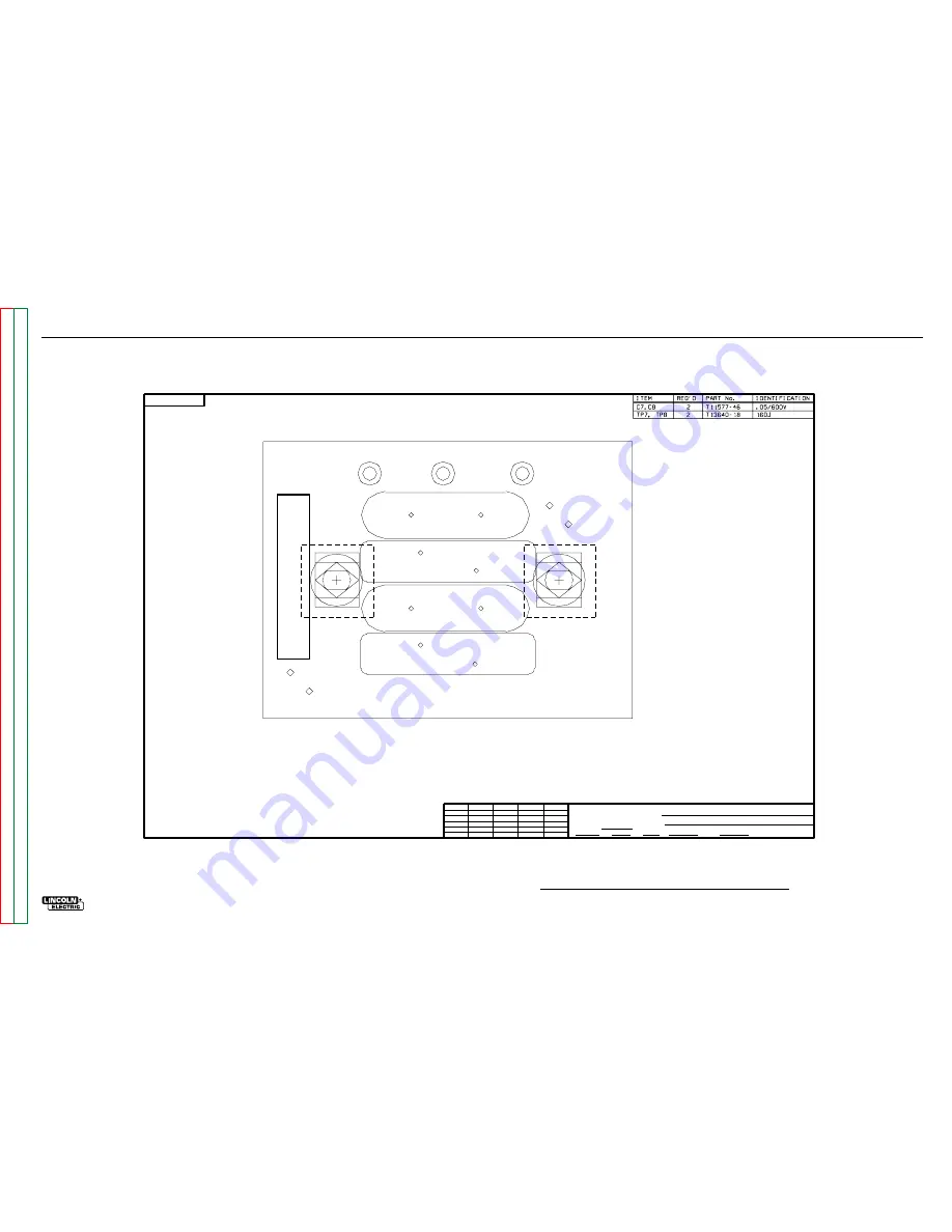
PC BOARD ASSEMBLY - SNUBBER

Ch'ge. Sht. No.

  2-19-93G  

  7-23-93C  


        TRANSFORMER WELDERS       

 OUTPUT SNUBBER P.C. BD. ASSEMBLY 

  C.S.    

    FULL    


 8-18-92


THE LINCOLN ELECTRIC CO.

CLEVELAND, OHIO U.S.A.

EQUIP.

TYPE

SCALE

SUBJECT

DR

DATE

CHK

REF.

SUP'S'D'G

SHT.

NO.

M

M

CAD

14312-1   

14312-1   

C7   

 TP7 

C8   

 TP8 

OUTPUT SNUBBER

GND

NEG

POS

M14312-1

G-7

Retur

n to Section TOC

Retur

n to Section TOC

Retur

n to Section TOC

Retur

n to Section TOC

Retur

n to Master TOC

Retur

n to Master TOC

Retur

n to Master TOC

Retur

n to Master TOC

Содержание MULTI-SOURCE

Страница 1: ...Safety Depends on You Lincoln arc welding and cutting equipment is designed and built with safety in mind However your overall safety can be increased by proper installation and thoughtful operation on your part DO NOT INSTALL OPERATE OR REPAIR THIS EQUIPMENT WITHOUT READING THIS MANUAL AND THE SAFETY PRECAUTIONS CONTAINED THROUGHOUT And most importantly think before you act and be careful Return ...

Страница 2: ...RIOUS INJURY OR DEATH KEEP CHILDREN AWAY PACEMAKER WEARERS SHOULD CONSULT WITH THEIR DOCTOR BEFORE OPERATING Read and understand the following safety highlights For additional safety information it is strongly recommended that you purchase a copy of Safety in Welding Cutting ANSI Standard Z49 1 from the American Welding Society P O Box 351040 Miami Florida 33135 or CSA Standard W117 2 1974 A Free ...

Страница 3: ...d the work or metal to be welded to a good electrical earth ground 3 f Maintain the electrode holder work clamp welding cable and welding machine in good safe operating condition Replace damaged insulation 3 g Never dip the electrode in water for cooling 3 h Never simultaneously touch electrically hot parts of electrode holders connected to two welders because voltage between the two can be the to...

Страница 4: ...ing area If this is not possible cover them to prevent the welding sparks from starting a fire Remember that welding sparks and hot materials from welding can easily go through small cracks and openings to adjacent areas Avoid welding near hydraulic lines Have a fire extinguisher readily available 6 b Where compressed gases are to be used at the job site special precautions should be used to preve...

Страница 5: ...à proximité au soudage à l aide d écrans appropriés et non inflammables 4 Des gouttes de laitier en fusion sont émises de l arc de soudage Se protéger avec des vêtements de protection libres de l huile tels que les gants en cuir chemise épaisse pan talons sans revers et chaussures montantes 5 Toujours porter des lunettes de sécurité dans la zone de soudage Utiliser des lunettes avec écrans laterau...

Страница 6: ...SOURCE Page Safety i iv Installation Section A Operation Section B Accessories Section C Maintenance Section D Theory of Operation Section E Troubleshooting and Repair Section F Electrical Diagrams Section G Parts Manual P 367 SERIES RETURN TO MAIN MENU ...

Страница 7: ...lation Section A Technical Specifications A 2 Safety Precautions A 3 Select Proper Location A 3 Stacking A 3 Tilting A 3 Electrical Input Connections A 3 Fuse and Wire Sizes A 4 Input and Grounding Connections A 4 Reconnect Procedure A 4 Output Connections A 5 Paralleling A 5 Multi Source Output Limitations A 5 Distribution Box A 5 Pig Tail Leads and Connections A 5 ...

Страница 8: ...E ONLY CURRENT RANGE OCV RECOMMENDED INPUT WIRE AND FUSE SIZES Standard Voltage Frequency 380 415 50 400 60 440 50 460 60 550 50 575 60 99A 98A 79A 83A 66A 69A Input Current at Rated Output 100 Duty Cycle RATED OUTPUT INPUT VOLTAGE 380 415 460 575 FUSE SUPER LAG OR BREAKER SIZE AMPS 150 Amp 125 Amp 100 Amp TYPE 75 C GROUND WIRE IN CONDUIT AWG IEC MM2 SIZES 6 16 6 16 8 10 TYPE 75 C COPPER WIRE IN C...

Страница 9: ...achine check that the input sup ply voltage phase and frequency are the same as the machine s voltage phase and frequency as specified on the machine s rating plate on the Case Front Assembly Control Panel Connect input power supply by removing the rear access panel and connecting to the three line terminals on the input panel See Figure A 2 for location of the machine s input cable entry opening ...

Страница 10: ...e Input Connection Diagram located on the inside of Case Back Input Access Door The conductor and fuse sizes in the Technical Specification Section are per the National Electrical Code The sizes are in American Wire Gauge and the next largest standard metric size in mm2 National and local codes must be consulted before connecting a machine Protect the input circuit with the super lag fuses or dela...

Страница 11: ...rcs The number of Multi Weld 350s the procedures used and the combined duty cycle of the arcs are only limit ed by the 40 000 36 000 watts on 50Hz watt rating of the Multi Source supply The machine is IP 23S rated and is designed for outdoor applications DISTRIBUTION BOX The Multi Weld Distribution Box K1736 1 is available for interconnection of the Multi System using the same pig tail connection ...

Страница 12: ...NOTES A 6 A 6 MULTI SOURCE Return to Section TOC Return to Section TOC Return to Section TOC Return to Section TOC Return to Master TOC Return to Master TOC Return to Master TOC Return to Master TOC ...

Страница 13: ... TOC TABLE OF CONTENTS OPERATION SECTION Operation Section B Safety Instructions B 2 General Description B 3 Recommended Equipment Processes B 3 Design Features and Advantages B 3 Recommended Equipment Connections B 4 Controls and Settings B 4 Section B 1 Section B 1 MULTI SOURCE ...

Страница 14: ...ork and ground Always wear dry insulating gloves FUMES AND GASES can be dangerous Keep your head out of fumes Use ventilation or exhaust to remove fumes from breathing zone WELDING SPARKS can cause fire or explosion Keep flammable material away Do not weld on closed containers ARC RAYS can burn eyes and skin Wear eye ear and body protection Only qualified personnel should operate this equipment Se...

Страница 15: ...sable the machine output The transformer iron rear thermostat senses that the lamination and thus the coil insulation is over heating which can happen even if the output is disabled This thermostat will interrupt power to the Control board causing the input contactor to open until the iron cools The only user controls are an on off toggle Power switch that energizes the machine and a 10 A cir cuit...

Страница 16: ...indicates that the machines output voltage is within the safe operating range 6 DIGITAL METER Provides the user with an indication of the percentage of avail able power For 1 0 Cable K852 70 K1759 70 K852 90 K1759 90 Twist Mate Male Connector Twist Mate Female Connector Twist Mate Male Connector Twist Mate Female Connector For 3 0 Cable The Multi weld 350 has multi process capability and may be us...

Страница 17: ...n to Master TOC Return to Master TOC Return to Master TOC TABLE OF CONTENTS ACCESSORIES Accessories Section C Factory Installed Options Accessories C 2 Field Installed Options Accessories C 2 Section C 1 Section C 1 MULTI SOURCE ...

Страница 18: ...e arc wire feeder K1788 1 Roll Cage Protect power source facilitate moving store cable K1806 1 Multi Weld Four pack Mounting lift rack for M S and four M Ws K1807 1 Multi Weld Eight Pack Mounting lift rack for M S and eight M Ws S20428 Paralleling Kit Allows two machines to equally share double load ACCESSORIES C 2 C 2 MULTI SOURCE Return to Section TOC Return to Section TOC Return to Section TOC ...

Страница 19: ...NTS MAINTENANCE MULTI SOURCE Return to Master TOC Return to Master TOC Return to Master TOC Return to Master TOC Maintenance Section D Safety Precautions D 2 Routine and Periodic Maintenance D 2 Major Component Locations D 3 ...

Страница 20: ...dic maintenance tightening cleaning or replacing parts See Figure D 1 Perform the following daily 1 Check that no combustible materials are in the welding or cutting area around the machine 2 Remove the debris dust dirt or materials that could block the air flow to the machine for cooling 3 Inspect the welding cables for any splits or punc tures in the cable jacket or any condition that would affe...

Страница 21: ...turn to Section TOC Return to Section TOC Return to Master TOC Return to Master TOC Return to Master TOC Return to Master TOC 1 Case Front Assembly 2 Case back Assembly 3 Fan 4 Base 5 Sides 6 Roof 7 Rectifier Assembly MULTI SOURCE MULTI SOURCE OU TP UT TH ER MA L FA N PO WE R ON OF F OU TP UT WA RN ING 1 2 3 4 5 6 7 ...

Страница 22: ...NOTES D 4 D 4 MULTI SOURCE Return to Section TOC Return to Section TOC Return to Section TOC Return to Section TOC Return to Master TOC Return to Master TOC Return to Master TOC Return to Master TOC ...

Страница 23: ...ECTRODE TERMINAL T1 MAIN TRANSFORMER INPUT CONTACTOR CONTROL TRANSFORMER THERMOSTAT SWITCH CONTROL BOX RECTIFIER FAN R E C O N N E C T SURGE NOISE FILTER T2 FAN VOLTAGE 120 VAC CONTACTOR 32 VAC 32 VAC 32 VAC TO CONTROL BOARD Theory of Operation Section Section E General Description E 2 Input Voltage Filter Contactor and Control Transformer E 2 Main Transformer Control Board Cooling Fan Motor Digit...

Страница 24: ...nsformer has a single primary to secondary ratio no taps that spans the full input range up to 600VAC The sec ondary voltage developed on the secondary of the control transformer is applied to the control box full wave bridge rectifier via a thermostat and the input power switch The input contactor which is activat ed and controlled by the control board applies the three phase AC input voltage to ...

Страница 25: ...al thermostats This feedback information is processed by the control board The control board then sends the appropriate gate firing signals to the firing board output informa tion to the digital meter and command signals to the cooling fan motor and the input contactor The cooling fan is controlled by the control board The F A N fan as needed will be activated with an output current greater than 2...

Страница 26: ...Rectifiers SCRs controlled by that particular phase The firing circuit supplies the proper amount of energy to the gates of the power SCRs When the gate signal is applied at the correct time the SCR will turn on and conduct cur rent The amount of ON timer versus OFF time determines the output of the machine See SCR Operation A capacitor filter and resistor are connected across the output leads on ...

Страница 27: ...t normal output loads The opening of either the secondary or SCR heat sink thermostat s will disable the machine s output and cause the amber thermal light to glow The thermostat located at the rear of the main trans former iron senses the lamination temperature and thus the coil insulation temperature and will interrupt power to the control board causing the input contac tor to open until the iro...

Страница 28: ...athode When an AC supply voltage is applied to the SCR the device spends a certain portion of the AC cycle time in the on state and the remainder of the time in the off state The amount of time spent in the ON state is controlled by the gate An SCR is fired by a short burst of current into the gate This gate pulse must be more positive than the cathode voltage Since there is a standard PN junc tio...

Страница 29: ...tage Test F 17 Static SCR Test F 21 Active SCR Test F 25 Control Board Test F 31 Firing Board Test F 35 Multi Source Meter Accuracy Test F 39 Normal Open Circuit Voltage Waveform No Load F 41 Abnormal Open Circuit Voltage Waveform 1 SCR Not Functioning No Load F 42 Typical SCR Gate Voltage Waveform No Load F 43 Replacement Procedures F 45 Input Contactor Cleaning and or Replacement F 45 Control Bo...

Страница 30: ...hibit Find the list ing that best describes the symptom that the machine is exhibiting Symptoms are grouped into two main categories Output Problems and Function Problems Step 2 PERFORM EXTERNAL TESTS The second column labeled POSSIBLE AREAS OF MISADJUSTMENT S lists the obvious external possibilities that may contribute to the machine symptom Perform these tests checks in the order listed In gener...

Страница 31: ...ely put it back in the sta tic shielding bag If the PC Board uses protective shorting jumpers don t remove them until installation is complete If you return a PC Board to The Lincoln Electric Company for credit it must be in the static shield ing bag This will prevent further damage and allow proper failure analysis 4 Perform any necessary PC Board calibration pro cedures See the flow chart on the...

Страница 32: ...t oper ate The white power light is ON 1 Check for blown or missing fuses in the input lines 2 Check the three phase input line voltage at the Multi Source The input voltage must match the rating plate and reconnect panel 1 Check the three phase input line voltage at the Multi Source The input line voltage must match the rating plate and reconnect panel 2 Turn the power switch OFF and wait a few s...

Страница 33: ...ximum welding output 40 000 watts on 60 Hz 36 000 watts on 50HZ 1 Check the welding cables for loose or faulty connections 2 Make certain the Multi Weld s are connected and operating properly 3 Check at the output terminals of the Multi Source for approximately 75 80VDC open circuit voltage If this voltage is present the problem is most likely external to the Multi Source machine 1 Check all three...

Страница 34: ...e green light is OFF and the input contactor opens 1 Remove all external welding cables from the Multi Source machine If the open circuit voltage 75 80VDC is present and constant at the output ter minals there may be a short circuit external to the Multi Source Check the welding cables and the Multi Weld machines 2 If the problem is not resolved with the welding cables removed there is a fault wit...

Страница 35: ...ing output the fan does NOT run and the digital output display never reads a value greater than 100 1 The machine is being over loaded and thus overheated Reduce the load to conform to the rated output limits of the Multi Source machine See the Technical Specifications 1 The machine may be internally clogged with dirt and dust Clean the machine with clean dry compressed air 2 The cooling vents may...

Страница 36: ...form the test repairs safely con tact the Lincoln Electric Service Department for electrical troubleshooting assistance before you proceed Call 1 800 833 9353 OUTPUT PROBLEMS SYMPTOMS POSSIBLE AREAS OF MISADJUSTMENT S RECOMMENDED COURSE OF ACTION FUNCTIONS PROBLEMS The Multi Source machine will not shut off when the ON OFF switch is in the OFF position 1 Remove all external loading to the Multi So...

Страница 37: ...to avoid electrical shock please observe all safety notes and precautions detailed throughout this manual If for any reason you do not understand the test procedures or are unable to perform the tests repairs safely contact the Lincoln Electric Service Department for technical troubleshooting assistance before you proceed Call 800 833 9353 WELD TEST DESCRIPTION This test will determine if the corr...

Страница 38: ...OC TEST PROCEDURE 1 Disconnect main AC input power to the machine 2 Remove the Top and Right case side 3 Locate the Control Transformer T2 on the left side of the input box facing the back of the machine See Figure F 1 4 Locate the Control Transformer primary leads H1 H2 See Wiring Diagram See Figure F 1 5 Locate control transformer terminals X1 and X3 See Figure F 1 FIGURE F 1 CONTROL TRANSFORMER...

Страница 39: ...t secondary voltages See Table F 1 NOTE If the correct main AC input power to the Control Transformer is present and the secondary voltages are not correct the Control Transformer may be faulty Replace TABLE F 1 Primary H1 H2 Voltage Approximate Secondary Voltage X1 X3 575 VAC Approximate Secondary Resistance X1 X3 460 VAC 380 VAC 34 50 VAC 28 50 VAC 0 5 Ohms 60 Ohms Approximate Primary Resistance...

Страница 40: ... Master TOC Return to Master TOC Return to Master TOC Return to Master TOC NOTE If the secondary voltage is not pre sent at terminal X3 but is present at terminal X2 the internal thermostat is faulty See Figure F 2 7 Replace any leads previously removed 8 Replace right side and roof X3 Thermostat X2 X1 Secondary FIGURE F 2 Thermostat TROUBLESHOOTING REPAIR ...

Страница 41: ...our safety and to avoid electrical shock please observe all safety notes and precautions detailed throughout this manual If for any reason you do not understand the test procedures or are unable to perform the tests repairs safely contact the Lincoln Electric Service Department for technical troubleshooting assistance before you proceed Call 800 833 9353 WELD TEST DESCRIPTION This test will determ...

Страница 42: ...on High voltage is present at terminals 5 Carefully apply the correct voltage to the machine and turn the power switch S1 ON 6 Check for approximately 1 amp of current flow at the contactor coil This current is supplied by the Control Board NOTE The pull in coil current is designed to be about 5 amps for 100ms occurring about one second after the power switch is closed Without this current pulse t...

Страница 43: ... If the contactor does NOT activate the input contactor is faulty Replace the input contactor 4 With the contactor activated check the continuity across the contacts Zero ohms or very low resistance is normal See Figure F 4 If the resistance is high the input contactor is faulty Replace the input contactor 5 When the contactor is NOT activated the resistance should be infinite or very high across ...

Страница 44: ...F 16 F 16 NOTES MULTI SOURCE Return to Section TOC Return to Section TOC Return to Section TOC Return to Section TOC Return to Master TOC Return to Master TOC Return to Master TOC Return to Master TOC ...

Страница 45: ... avoid electrical shock please observe all safety notes and precautions detailed throughout this manual If for any reason you do not understand the test procedures or are unable to perform the tests repairs safely contact the Lincoln Electric Service Department for technical troubleshooting assistance before you proceed Call 800 833 9353 WELD TEST DESCRIPTION This test will determine if the correc...

Страница 46: ...E If proper voltage is not present in any or all of the three phases check input fuses and leads 5 Test with an AC voltmeter for proper main AC input voltage from the output side of the input contactor 1CR See Wiring Diagram See Figure F 5 T1 to T2 T2 to T3 T1 to T3 a If the correct voltage is present the contactor is working properly b If the correct voltage is not present for any or all of the t...

Страница 47: ... the 120 VAC is not present check for loose or faulty wiring If necessary untape and track the continuity of leads 250 and 251 through the entire harness See the Wiring Diagram b If the wiring is good and the 120 VAC is not present then the main trans former may be faulty 9 Test with an AC voltmeter for 32 VAC for each phase angle winding as shown See Figure F 6 See Wiring Diagram NOTE If the main...

Страница 48: ...F 20 F 20 NOTES MULTI SOURCE Return to Section TOC Return to Section TOC Return to Section TOC Return to Section TOC Return to Master TOC Return to Master TOC Return to Master TOC Return to Master TOC ...

Страница 49: ...void electrical shock please observe all safety notes and precautions detailed throughout this manual If for any reason you do not understand the test procedures or are unable to perform the tests repairs safely contact the Lincoln Electric Service Department for technical troubleshooting assistance before you proceed Call 800 833 9353 WELD TEST DESCRIPTION The Static SCR Test is a quick check to ...

Страница 50: ...urn to Section TOC Return to Master TOC Return to Master TOC Return to Master TOC Return to Master TOC 1 Remove main supply power to the machine 2 Remove the roof and case sides 3 Lower the front control panel 4 Remove Plug J4 from the firing board See Figure F 7 FIRING BOARD J5 J6 J8 J4 J7 Plug J4 FIGURE F 7 FIRING BOARD LED PLUG LOCATIONS ...

Страница 51: ...urposes See Wiring Diagram 5 Remove the red insulating paint from heat sink test points See Figure F 9 NOTE DO NOT DISASSEMBLE THE HEAT SINKS 6 Using an analog ohmmeter test the resis tance from anode to cathode of SCR 1 Reverse the meter leads and check from cathode to anode of SCR 1 R x 1000 scale See Figure F 9 a If a low resistance is indicated in either direction one of the SCRs may be faulty...

Страница 52: ...TOC 7 Repeat previous step s testing SCR 2 SCR 3 SCR 4 SCR 5 and SCR 6 To further check the SCRs functions use an SCR tester and proceed to Active SCR Test 8 When test is completed reconnect the positive bridge leads to the shunt 9 Reconnect any secondary leads removed from the SCRs 10 Reconnect Plug J4 into the firing board 11 Replace the case top sides and control panel Remove Red Paint Anode Ca...

Страница 53: ... electrical shock please observe all safety notes and precautions detailed throughout this manual If for any reason you do not understand the test procedures or are unable to perform the tests repairs safely contact the Lincoln Electric Service Department for technical troubleshooting assistance before you proceed Call 800 833 9353 WELD TEST DESCRIPTION The active SCR Test will determine if the de...

Страница 54: ...to Section TOC Return to Master TOC Return to Master TOC Return to Master TOC Return to Master TOC FIRING BOARD J5 J6 J8 J4 J7 Plug J4 1 Remove main supply power to the Multi Source 2 Remove the roof and case sides 3 Lower the front control panel and remove Plug J4 from the Firing Board See Figure F 10 FIGURE F 10 FIRING BOARD LED PLUG LOCATIONS ...

Страница 55: ...ion TOC Return to Master TOC Return to Master TOC Return to Master TOC Return to Master TOC Leads 4 Using a 9 16 wrench remove the two positive output leads connecting the out put bridge to the shunt See Figure F 11 This will partially electrically isolate the SCR bridge for testing purposes See the Wiring Diagram FIGURE F 11 Shunt and Lead Connections ...

Страница 56: ...TOC Return to Master TOC Return to Master TOC Return to Master TOC Return to Master TOC Remove Red Paint Anode Cathode 5 Remove the red insulating paint from heat sink test points See Figure F 12 6 Perform test procedure as follows Refer to Figure F 13 Repeat test for all six SCRs NOTE Do not disassemble the heat sinks FIGURE F 12 SCR Heat Sink Test Points ...

Страница 57: ...less than 4 5 volts A Connect SCR into the test circuit as shown A lead to anode C lead to cath ode and G lead to the gate B Close switch SW1 switch SW2 should open voltmeter should read zero If the voltmeter reads higher than zero than the SCR is shorted NOTE Do not disassemble the heat sinks 8 With switch SW1 closed close switch SW2 for two seconds and release The voltmeter should read 3 to 6 vo...

Страница 58: ...F 30 F 30 NOTES MULTI SOURCE Return to Section TOC Return to Section TOC Return to Section TOC Return to Section TOC Return to Master TOC Return to Master TOC Return to Master TOC Return to Master TOC ...

Страница 59: ...r factory warranty For your safety and to avoid electrical shock please observe all safety notes and precautions detailed throughout this manual If for any reason you do not understand the test procedures or are unable to perform the tests repairs safely contact the Lincoln Electric Service Department for technical troubleshooting assistance before you proceed Call 800 833 9353 WELD TEST DESCRIPTI...

Страница 60: ...ld be brightly lit Normal open circuit voltage OCV at the welding output terminals is approximately 80VDC This voltage can be checked at Plug J1 pin 1 lead 201 to Plug J1 pin 9 lead 222A If the voltage is correct but LED1 is not lit the control may be faulty See Figure F 15 6 LED 2 indicates the level of the control sig nal that is passed to the firing board The brightness of LED 2 is inversely pr...

Страница 61: ...hin range but the green light is not lit either the green light is faulty or the control board is faulty Normal operat ing voltage for the green light is about 3 5VDC A voltage of about 5 0VDC would indicate the light is open and the control board circuit is operating correctly This can be measured at Plug J1 pin 16 lead 232 to Plug J1 pin 15 lead 233 See Figure F 15 13 The yellow amber light loca...

Страница 62: ...F 34 F 34 NOTES MULTI SOURCE Return to Section TOC Return to Section TOC Return to Section TOC Return to Section TOC Return to Master TOC Return to Master TOC Return to Master TOC Return to Master TOC ...

Страница 63: ...e all safety notes and precautions detailed throughout this manual If for any reason you do not understand the test procedures or are unable to perform the tests repairs safely contact the Lincoln Electric Service Department for technical troubleshooting assistance before you proceed Call 800 833 9353 WELD TEST DESCRIPTION The Test determines whether or not the Firing Board is receiving the correc...

Страница 64: ... Use Table F 2 to check LED operation 6 Make certain that plug J7 jumper plug is in place See Figure F17 and the wiring diagram NOTE To verify that the control board is sending the correct output enable signal to the firing board check from plug J8 pin 7 lead 340 to plug J5 pin 12 lead 215 See Figure F 17 See the wiring diagram Normal voltage is approximately less than 1 0 VDC If not correct the c...

Страница 65: ...Main Transformer Test Also check resistors R3 and R4 located in the resistor bank Normal resistance is 50 ohms AC power is being supplied to the Firing Board from leads 285 and 286 connected through the resistor bank to the phase angle winding in the Main Transformer See Figure F 17 Normal voltage at leads 285 to 286 is 25 VAC The proper AC voltage may not be reaching the Firing Board Check for lo...

Страница 66: ...o Section TOC Return to Section TOC Return to Section TOC Return to Section TOC Return to Master TOC Return to Master TOC Return to Master TOC Return to Master TOC FIRING BOARD J6 J4 J7 Jumper Plug J5 J8 284 283 286 287 285 340 215 231 288 FIGURE F 17 FIRING BOARD PLUG PIN LOCATIONS ...

Страница 67: ...ill invalidate your factory warranty For your safety and to avoid electrical shock please observe all safety notes and precautions detailed throughout this manual If for any reason you do not understand the test procedures or are unable to perform the tests repairs safely contact the Lincoln Electric Service Department for technical troubleshooting assistance before you proceed Call 800 833 9353 W...

Страница 68: ...ver and the machine may be reassembled If the required results are not obtained proceed to the next sec tion PROCEDURE TO RECALIBRATE IF METER IS OUT OF RANGE If the measured current is within the acceptable cur rent range approximately 533 amps DC and the Multi Source digital display does not read approxi mately 100 then the meter must be recalibrated The Multi Source digital display is controlle...

Страница 69: ... Master TOC 0 volts 2 ms 50 volts This is the typical DC open circuit volt age waveform generated from a properly operating machine Note that each ver tical division represents 50 volts and that each horizontal division represents 2 mil liseconds in time Note Scope probes connected at machine output terminals probe to positive terminal probe to negative terminal Volts Div 50 V Div Horizontal Sweep...

Страница 70: ...50 volts This is NOT the typical DC output volt age waveform One output SCR is not functioning Note the gap in the wave form One SCR gate is disconnected to simulate an open or non functioning out put SCR Each vertical division repre sents 50 volts and each horizontal divi sion represents 2 milliseconds in time Note Scope probes connected at machine output terminals probe to positive terminal prob...

Страница 71: ...RM NO LOAD 0 volts 2 ms 1 volt This is the typical SCR gate pulse volt age waveform The machine was in an open circuit condition no load and operating properly Note that each verti cal division represents 1 volt and that each horizontal division represents 2 mil liseconds in time Note Scope probes connected at SCR gate and cathode probe to gate probe to cathode Volts Div 1 V Div Horizontal Sweep 2...

Страница 72: ...F 44 F 44 NOTES MULTI SOURCE Return to Section TOC Return to Section TOC Return to Section TOC Return to Section TOC Return to Master TOC Return to Master TOC Return to Master TOC Return to Master TOC ...

Страница 73: ...r and will invalidate your factory warranty For your safety and to avoid electrical shock please observe all safety notes and precautions detailed throughout this manual If for any reason you do not understand the test procedures or are unable to perform the tests repairs safely contact the Lincoln Electric Service Department for technical troubleshooting assistance before you proceed Call 800 833...

Страница 74: ...connected to the input contactor 5 Using a 7 16 nut driver remove the four bolts mounting the input contactor to the frame of the machine Note washer posi tions for replacement See Figure F 20 6 Disconnect leads 240 and 241 using quick connects located in loom 7 Carefully lift input contactor out of machine 8 For contactor cleaning or inspection see Figure F 21 REPLACEMENT PROCEDURE 1 Mount input ...

Страница 75: ...ESHOOTING REPAIR MULTI SOURCE Return to Section TOC Return to Section TOC Return to Section TOC Return to Section TOC Return to Master TOC Return to Master TOC Return to Master TOC Return to Master TOC FIGURE F 21 INPUT CONTACTOR CLEANING INSPECTION CONTACTOR COIL 240 241 ...

Страница 76: ...F 48 F 48 NOTES MULTI SOURCE Return to Section TOC Return to Section TOC Return to Section TOC Return to Section TOC Return to Master TOC Return to Master TOC Return to Master TOC Return to Master TOC ...

Страница 77: ...e operator and will invalidate your factory warranty For your safety and to avoid electrical shock please observe all safety notes and precautions detailed throughout this manual If for any reason you do not understand the test procedures or are unable to perform the tests repairs safely contact the Lincoln Electric Service Department for technical troubleshooting assistance before you proceed Cal...

Страница 78: ...f control box while facing the machine See Figure F 22 3 Disconnect plugs J2 J1 and J3 from the control board 4 Remove the four phillips head screws and associated washers from the corners of the control board See Figure F 23 5 Carefully remove the control board REPLACEMENT PROCEDURE 1 Replace the control board 2 Mount the control board to the machine in its proper position using the four phillips...

Страница 79: ...e operator and will invalidate your factory warranty For your safety and to avoid electrical shock please observe all safety notes and precautions detailed throughout this manual If for any reason you do not understand the test procedures or are unable to perform the tests repairs safely contact the Lincoln Electric Service Department for technical troubleshooting assistance before you proceed Cal...

Страница 80: ...g the machine See Figure F 24 3 Disconnect plugs J5 J8 and J4 from the firing board 4 Remove the four phillips head screws and associated washers from the corners of the firing board See Figure F 25 5 Carefully remove the firing board REPLACEMENT PROCEDURE 1 Replace the firing board 2 Mount the firing board to the machine in its proper position using the four phillips head screws and associated wa...

Страница 81: ...ory warranty For your safety and to avoid electrical shock please observe all safety notes and precautions detailed throughout this manual If for any reason you do not understand the test procedures or are unable to perform the tests repairs safely contact the Lincoln Electric Service Department for technical troubleshooting assistance before you proceed Call 800 833 9353 WELD DESCRIPTION The foll...

Страница 82: ... PROCEDURE 1 Disconnect input power to the machine 2 Using a 3 8 nut driver remove the case sides and roof 3 Locate label and remove leads 301 and 264 from the thermostat See Figure F 26 4 Lower the control panel using a 3 8 nut driver 5 Remove plug J4 from the firing board and feed the disconnected plug down through the hole in the bottom of the P C board control box L E F T S I D E L E F T S I D...

Страница 83: ...8 nut driver remove the right bolt mounting the SCR bridge to the front assembly The bolt is located below the control board See Figure F 28 9 Cut any necessary cable ties 10 Using a 1 2 nut driver remove the two mounting bolts on the right side of the machine mounting the SCR bridge to the main transformer 11 Using a 9 16 nut driver remove two bolts covered in red insulating paint on the left sid...

Страница 84: ...all leads and carefully maneuver SCR bridge out of the right side of the machine NOTE Upon reassembly apply a thin layer of Lincoln Electric T12837 Dow Corning 340 heat sink compound to all bolted electrical connections on the alu minum heat sinks UPON REASSEMBLY THE SCR BRIDGE ASSEMBLY MUST BE ELECTRICALLY ISOLATED FROM GROUND MINIMUM ACCEPTABLE RESISTANCE TO GROUND IS 500K OHMS FIGURE F 28 Mount...

Страница 85: ...ting studs Replacement will be made with a new SCR assembly 4 Replace snubber assembly if necessary DO NOT DISASSEMBLE THE SCR FROM THE HEAT SINK REPLACE THE SCR ONLY AS AN ASSEMBLY INSTALLATION OF INDIVIDUAL SCR HEAT SINK ASSEMBLIES NOTE Upon reassembly apply a thin layer of Lincoln T12837 Dow Corning 340 heat sink compound to all bolted elec trical connections on the aluminum heat sinks includin...

Страница 86: ...insulate 3 Replace the two 9 16 mounting bolts pre viously removed Be sure to position insu lation bushing washer and nut correctly See Figure F 26 4 Replace the two 1 2 mounting bolts on the right side of the machine previously removed These bolts mount the SCR bridge to the main transformer See Figure F 27 5 Replace any previously removed cable ties 6 Replace the 3 8 mounting screw previ ously r...

Страница 87: ... Open Circuit Volts 79 5 80 VDC PERFORM METER ACCURACY TEST RETEST AFTER REPAIR Testing is required after the removal of any mechanical part that could affect the machine s elec trical characteristics or if any electrical components are repaired or replaced NO LOAD READINGS FAN OFF Input Volts Phase Hertz Maximum Idle Amps Maximum Idle KW 380 3 50 15 0 2 0 400 3 50 20 0 2 25 415 3 50 25 0 2 5 460 ...

Страница 88: ...F 60 F 60 NOTES MULTI SOURCE Return to Section TOC Return to Section TOC Return to Section TOC Return to Section TOC Return to Master TOC Return to Master TOC Return to Master TOC Return to Master TOC ...

Страница 89: ...ON ELECTRICAL DIAGRAMS SECTION G WIRING DIAGRAM G 2 CONTROL PC BOARD SCHEMATIC G 3 CONTROL PC BOARD ASSEMBLY G 4 FIRING PC BOARD SCHEMATIC G 5 FIRING PC BOARD ASSEMBLY G 6 SNUBBER PC BOARD ASSEMBLY G 7 Return to Master TOC Return to Master TOC Return to Master TOC Return to Master TOC ...

Страница 90: ... PRIMARY COILS 380 415V CONNECTION TO T2 TO T1 3 POWER TO T2 TO T1 H2 H1 H2 H1 H2 H1 TO A SYSTEM GROUND PER NATIONAL ELECTRIC CODE T1 T1 T1 T2 MULTI SOURCE WIRING DIAGRAM 16 9 8 1 CONNECTORS VIEWED FROM INSERTION END ELECTRICAL SYMBOLS PER E1537 1 2 1 3 1 5 1 4 3 4 4 6 5 8 6 10 272 10 13 2000 L11414 253 J7 284 283 286 285 288 287 240 215 231 J8 J5 G1 G2 G3 G4 G5 G6 1 2 3 4 5 6 7 8 9 10 1 2 3 4 5 6...

Страница 91: ...C Return to Section TOC Return to Master TOC Return to Master TOC Return to Master TOC Return to Master TOC ELECTRICAL DIAGRAMS G 3 SCHEMATIC CONTROL PC BOARD G 3 NOTE This diagram is for reference only It may not be accurate for all machines covered by this manual ...

Страница 92: ...AMP QUAD HIGH PERF 1014 X2 X3 X4 X5 4 S15128 18 OP AMP QUAD HIGH PERF 33074 X6 X7 2 S15128 11 IC COMPARATOR QUAD 2901N X8 1 S15018 9 IC CMOS MULTIVBRTR_MONO_DUAL_4538 SS X9 X10 2 S15018 13 IC CMOS TIMER PROGRAMMABLE 4536 SS X11 1 M15458 4 IC PWM CONTROLLER IMODE 2842A X12 1 S15128 10 VOLTAGE REF ADJ PRECISION 431I X13 1 S18395 3 REGULATOR HEAT SINKASBLY S15128 5 S18104 3 DESCRIPTION PART NO PC BOA...

Страница 93: ...rn to Section TOC Return to Master TOC Return to Master TOC Return to Master TOC Return to Master TOC ELECTRICAL DIAGRAMS G 5 SCHEMATIC FIRING PRINTED CIRCUIT BOARD G 5 NOTE This diagram is for reference only It may not be accurate for all machines covered by this manual ...

Страница 94: ...161 R214 R196 R160 R216 R198 R162 R243 R200 R182 R242 R199 R181 R46 R45 R44 R234 R203 R204 R217 R208 R220 R175 R168 R93 R85 R240 R193 R165 R237 R190 R141 R247 R186 R137 R213 R180 R98 R225 R173 R90 R238 R191 R142 R248 R187 R138 R209 R210 R211 R212 R176 R177 R178 R179 R94 R95 R96 R97 R221 R222 R223 R224 R169 R170 R171 R172 R86 R87 R88 R89 R219 R185 R245 R206 R246 R184 R163 R167 R189 R139 R92 R250 R2...

Страница 95: ...y result in danger to the Machine Operator or Technician Improper PC board repairs could result in damage to the machine ELECTRICAL DIAGRAMS G 7 PC BOARD ASSEMBLY SNUBBER Ch ge Sht No 2 19 93G 7 23 93C TRANSFORMER WELDERS OUTPUT SNUBBER P C BD ASSEMBLY C S FULL 8 18 92 THE LINCOLN ELECTRIC CO CLEVELAND OHIO U S A EQUIP TYPE SCALE SUBJECT DR DATE CHK REF SUP S D G SHT NO M M CAD 14312 1 14312 1 C7 ...

Страница 96: ...__________________________________ ___________________________________________________________________________ ___________________________________________________________________________ ___________________________________________________________________________ ___________________________________________________________________________ _____________________________________________________________...

Отзывы: