


2
SAFETY
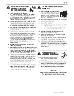
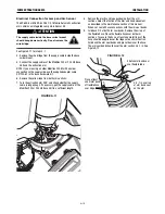
FUME EXTRACTION ARMS
As a rule of thumb, for many mild steel electrode, if the air is visibly
clear and you are comfortable, then the ventilation is generally
adequate for your work. The most accurate way to determine if the
worker exposure does not exceed the applicable exposure limit for
compounds in the fumes and gases is to have an industrial hygienist
take and analyze a sample of the air you are breathing. This is
particularly important if you are welding with stainless, hardfacing or
Special Ventilation products. All Lincoln MSDS have a maximum fume
guideline number. If exposure to total fume is kept below that
number, exposure to all fume from the electrode (not coatings or
plating on the work) will be below the TLV.
There are steps that you can take to identify hazardous substances in
your welding environment. Read the product label and material safety
data sheet for the electrode posted in the work place or in the
electrode or flux container to see what fumes can be reasonably
expected from use of the product and to determine if special
ventilation is needed. Secondly, know what the base metal is and
determine if there is any paint, plating, or coating that could expose
you to toxic fumes and/or gases. Remove it from the metal being
welded, if possible. If you start to feel uncomfortable, dizzy or
nauseous, there is a possibility that you are being overexposed to
fumes and gases, or suffering from oxygen deficiency. Stop welding
and get some fresh air immediately. Notify your supervisor and co-
workers so the situation can be corrected and other workers can
avoid the hazard. Be sure you are following these safe practices, the
consumable labeling and MSDS to improve the ventilation in your
area. Do not continue welding until the situation has been corrected.
NOTE: The MSDS for all Lincoln consumables is available on Lincoln’s web-
site: www.lincolnelectric.com
Before we turn to the methods available to control welding fume
exposure, you should understand a few basic terms:
Natural Ventilation
is the movement of air through the
workplace caused by natural forces. Outside, this is usually
the wind. Inside, this may be the flow of air through open
windows and doors.
Mechanical Ventilation
is the movement of air through the
workplace caused by an electrical device such as a portable
fan or permanently mounted fan in the ceiling or wall.
Source Extraction
(Local Exhaust) is a mechanical device
used to capture welding fume at or near the arc and filter
contaminants out of the air.
The ventilation or exhaust needed for your application depends upon
many factors such as:
• Workspace volume
• Workspace configuration
• Number of welders
• Welding process and current
• Consumables used (mild steel, hardfacing, stainless, etc.)
• Allowable levels (TLV, PEL, etc.)
• Material welded (including paint or plating)
• Natural airflow
Your work area has adequate ventilation when there is enough
ventilation and/or exhaust to control worker exposure to hazardous
materials in the welding fumes and gases so the applicable limits for
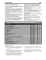
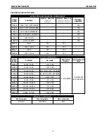
those materials is not exceeded. See chart of TLV and PEL for Typical
Electrode Ingredients, the OSHA PEL (Permissible Exposure Limit), and
the recommended guideline, the ACGIH TLV (Threshold Limit Value),
for many compounds found in welding fume.
Ventilation
There are many methods which can be selected by the user to
provide adequate ventilation for the specific application. The following
section provides general information which may be helpful in
evaluating what type of ventilation equipment may be suitable for
your application. When ventilation equipment is installed, you should
confirm worker exposure is controlled within applicable OSHA PEL
and/or ACGIH TLV. According to OSHA regulations, when welding and
cutting (mild steels), natural ventilation is usually considered
sufficient to meet requirements, provided that:
1. The room or welding area contains at least 10,000 cubic feet
(about 22' x 22' x 22') for each welder.
2. The ceiling height is not less than 16 feet.
3. Cross ventilation is not blocked by partitions, equipment, or
other structural barriers.
4. Welding is not done in a confined space.
Spaces that do not meet these requirements should be equipped with
mechanical ventilating equipment that exhausts at least 2000 CFM of
air for each welder, except where local exhaust hoods or booths, or
air-line respirators are used.
Important Safety Note:
When welding with electrodes which require special
ventilation such as stainless or hardfacing (see
instructions on container or MSDS) or on lead or
cadmium plated steel and other metals or coatings which
produce hazardous fumes, keep exposure as low as
possible and below exposure limit values (PEL and TLV)
for materials in the fume using local exhaust or
mechanical ventilation. In con ned spaces or in some
circumstances, for example outdoors, a respirator may
be required if exposure cannot be controlled to the PEL
or TLV. (See MSDS and chart of TLV and PEL for Typical
Electrode Ingredients.) Additional precautions are also
required when welding on galvanized steel.
Содержание K1655-10-LTA 2.0
Страница 43: ...ii THIS PAGE INTENTIONALLY LEFT BLANK...
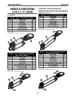
Страница 57: ...P 966 C jpg LFA 3 1 K2633 5 General Assembly LFA 3 1 K2633 5 1 3 3 4 5 5 5 5 6 10 12 11 9 8 2 7 8 14 13...
Страница 59: ...P 967 C jpg General Assembly 4 LFA 3 1 K2633 6 Printed 02 11 2016 at 10 26 47 Produced by Enigma...
Страница 61: ...P 968 C jpg LFA 4 1 K2633 7 General Assembly LFA 4 1 K2633 7 14 13...
Страница 63: ...P 969 C jpg LFA 4 1 K2633 8 General Assembly LFA 4 1 K2633 8 14 13...
Страница 64: ...ii THIS PAGE INTENTIONALLY LEFT BLANK...
Страница 65: ...ii THIS PAGE INTENTIONALLY LEFT BLANK...


