


English 8 English
Controls and Operational Features
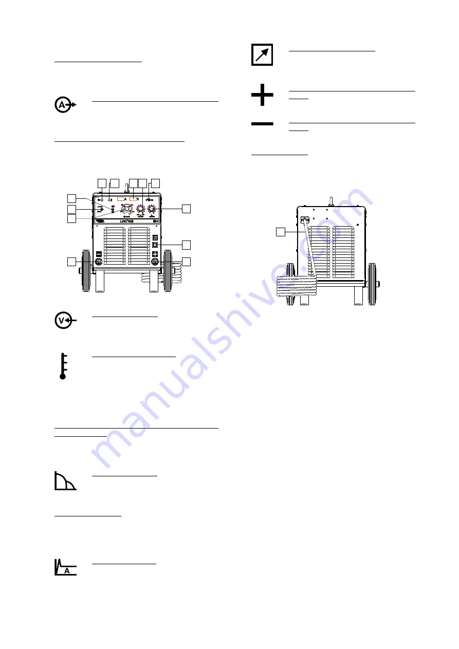
1. Power Switch ON/OFF (I/O): Controls the input power
to the machine. Be sure the power source is
connected to the mains supply before turning power
on (”I”).
2.
Welding Current Knob Control:
Potentiometer used to set the output
current on the range 30A - 400A (also
during welding).
3. Output Current Control Range Switch: It allows
selection of the desired welding current range:
LOW range (30A - 200A)
HIGH range (50A - 400A).
1
4
5
6 7
8
9
2
10
11
12
3
Figure 2.
4. Power Indicator Light: After input power is
connected and the power switch is turned
on, this lamp will light up to indicate the
machine is ready to weld.
5. Thermal Overload Indicator: This lamp will
light up when the machine is overheated
and the output has been turned off. This
can occur if the ambient temperature is
above 40°C or the duty cycle of the machine has been
exceeded. Leave the machine on to allow the internal
components to cool, when the lamp turns off normal
operation is possible.
6. Digital Welding Current and Voltage Meter with
memory feature: Shows the present value of the
welding current and voltage during welding; after
welding it continues to display the average welding
current and voltage for 5 seconds.
7. ARC FORCE Control: The output current
is temporarily increased to clear short
circuit connections between the electrode
and the workpiece.
8. Local/Remote Switch: Remote Control Unit K10095-
1-15M and K870 can be used with this machine. It
changes control of the Output Current from the
machine Welding Current [2] to the K10095-1-15M or
K870 and vice versa.
9. HOT START Control: Value in percentage
of nominal value welding current during
arc start current. The control is used to set
the level of the increased current and arc start current
is made easy.
10. Remote Control Connector: If a remote
control is used, it will be connected to the
remote connector (see "Accessories"
chapter).
11. Positive Output Socket for the welding
circuit: For connecting an electrode holder
with lead / work lead.
12. Negative Output Socket for the welding
circuit: For connecting an electrode holder
with lead / work lead.
13. Power lead (5m): Connect the supply plug to the
existing input cable that is rated for the machine as
indicated in this manual, and conforms to all applicable
standards. This connection shall be performed only by
a qualified person.
13
Figure 3.
Welding SMAW (MMA) process
LINC 406
does not include the electrode holder with lead
necessary and the work lead for SMAW welding, but the
one can be purchased separately (see "Accessories"
chapter).
For starting welding process with SMAW process you
should:
First turn the machine off.
Determine the electrode polarity for the electrode to be
used. Consult the electrode data for this information.
Connect output lead to output socket [11, 12] of the
machine and lock them.
Connect the work cable to the welding piece with the
work clamp.
Install the proper electrode in the electrode holder.
Connect the main plug to the outlet mains socket.
Turn the welding machine on.
Set the Local/Remote Switch in required position: local
or remote.
Set the required welding current by welding current
knob control [8].
Obeying appropriate rules you can begin to weld.


