Lincoln Electric INVERTEC V276 Скачать руководство пользователя страница 5

WELDING AND CUTTING

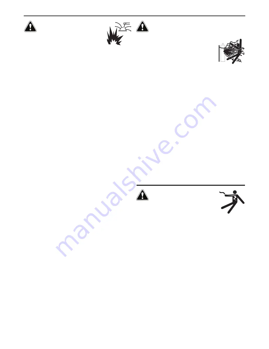
SPARKS CAN CAUSE

FIRE OR EXPLOSION.

6.a. Remove fire hazards from the welding area. If

this is not possible, cover them to prevent the welding sparks
from starting a fire. Remember that welding sparks and hot
materials from welding can easily go through small cracks and
openings to adjacent areas. Avoid welding near hydraulic lines.
Have a fire extinguisher readily available.

6.b. Where compressed gases are to be used at the job site, special

precautions should be used to prevent hazardous situations.
Refer to “Safety in Welding and Cutting” (ANSI Standard Z49.1)
and the operating information for the equipment being used.  

  6.c. When not welding, make certain no part of the electrode circuit is

touching the work or ground. Accidental contact can cause
overheating and create a fire hazard.

6.d. Do not heat, cut or weld tanks, drums or containers until the

proper steps have been taken to insure that such procedures 
will not cause flammable or toxic vapors from substances inside.
They can cause an explosion even though they have been
“cleaned”. For information, purchase “Recommended Safe
Practices for the Preparation for Welding and Cutting of
Containers and Piping That Have Held Hazardous Substances”,
AWS F4.1 from the American Welding Society 
(see address above).

6.e. Vent hollow castings or containers before heating, cutting or

welding. They may explode.

6.f. Sparks and spatter are thrown from the welding arc. Wear oil free

protective garments such as leather gloves, heavy shirt, cuffless
trousers, high shoes and a cap over your hair. Wear ear plugs
when welding out of position or in confined places. Always wear
safety glasses with side shields when in a welding area.

6.g. Connect the work cable to the work as close to the welding area

as practical. Work cables connected to the building framework or
other locations away from the welding area increase the
possibility of the welding current passing through lifting chains,
crane cables or other alternate circuits. This can create fire
hazards or overheat lifting chains or cables until they fail.

6.h. Also see item 1.c.

6.I. Read and follow NFPA 51B “Standard for Fire Prevention During

Welding, Cutting and Other Hot Work”, available from NFPA, 1
Batterymarch Park, PO box 9101, Quincy, MA 022690-9101.

6.j. Do not use a welding power source for pipe thawing.

CYLINDER MAY EXPLODE IF

DAMAGED.

7.a. Use only compressed gas cylinders containing

the correct shielding gas for the process used
and properly operating regulators designed for
the gas and pressure used. All hoses, fittings,
etc. should be suitable for the application and
maintained in good condition.

7.b. Always keep cylinders in an upright position securely chained to

an undercarriage or fixed support.

7.c. Cylinders should be located:

Away from areas where they may be struck or subjected
to physical damage.

A safe distance from arc welding or cutting operations
and any other source of heat, sparks, or flame.

7.d. Never allow the electrode, electrode holder or any other

electrically “hot” parts to touch a cylinder.

7.e. Keep your head and face away from the cylinder valve outlet

when opening the cylinder valve.

7.f. Valve protection caps should always be in place and hand tight

except when the cylinder is in use or connected for use.

7.g. Read and follow the instructions on compressed gas cylinders,

associated equipment, and CGA publication P-l, “Precautions for
Safe Handling of Compressed Gases in Cylinders,” available from
the Compressed Gas Association,  14501 George Carter Way
Chantilly, VA 20151.

FOR ELECTRICALLY

POWERED EQUIPMENT.

8.a. Turn off input power using the disconnect

switch at the fuse box before working on 
the equipment.

8.b. Install equipment in accordance with the U.S. National Electrical

Code, all local codes and the manufacturer’s recommendations.

8.c. Ground the equipment in accordance with the U.S. National

Electrical Code and the manufacturer’s recommendations.

Refer to

http://www.lincolnelectric.com/safety

for additional safety information.

SAFETY

Safety 04 of 04 - 5/16/2018

Содержание INVERTEC V276

Страница 1: ...egister Authorized Service and Distributor Locator www lincolnelectric com locator IM10586 Issue Date Feb 21 Lincoln Global Inc All Rights Reserved For use with machines having Code Numbers 13079 1308...

Страница 2: ...A LARGE ROOM OR OUTDOORS natural ventilation may be adequate if you keep your head out of the fumes See below USE NATURAL DRAFTS or fans to keep the fumes away from your face If you develop unusual s...

Страница 3: ...t engine parts and igniting Do not spill fuel when filling tank If fuel is spilled wipe it up and do not start engine until fumes have been eliminated 1 d Keep all equipment safety guards covers and d...

Страница 4: ...m to ANSI Z87 I standards 4 b Use suitable clothing made from durable flame resistant material to protect your skin and that of your helpers from the arc rays 4 c Protect other nearby personnel with s...

Страница 5: ...nt passing through lifting chains crane cables or other alternate circuits This can create fire hazards or overheat lifting chains or cables until they fail 6 h Also see item 1 c 6 I Read and follow N...

Страница 6: ...pri s et non inflamma bles 4 Des gouttes de laitier en fusion sont mises de l arc de soudage Se prot ger avec des v tements de protection libres de l huile tels que les gants en cuir chemise paisse pa...

Страница 7: ...PUT FILTER CAPACITOR DISCHARGE PROCEDURE D 1 ROUTINE MAINTENANCE D 2 FILTER CAPACITOR CONDITIONING D 2 LOCATION OF MAINTENANCE COMPONENTS D 3 TROUBLESHOOTING SECTION E DIAGRAMS SECTION F PARTS LIST PA...

Страница 8: ...AMPS 27 25 13 11 35 33 17 14 37 19 16 23 14 13 13 12 26 16 16 13 13 IDLE POWER 120W Max IDLE POWER 120W Max EFFICIENCY RATED OUTPUT 85 EFFICIENCY RATED OUTPUT 85 OUTPUT CONDITIONS 200A 28V 100 250A 30...

Страница 9: ...the fuse holder in the main disconnect panel INPUT SUPPLY CONNECTIONS Be sure the voltage phase and frequency of the input power is as specified on the rating plate located on the rear of the Supply...

Страница 10: ...F 208V 220 230V 380 415V 440 460V 575V A I NPUT VOLTAGE RANGE removed Do not operate with wraparound inspecting or servicing machine Disconnect input power before IF MACHINE CEASES TO OPERATE NO METER...

Страница 11: ...able connections 1 Remove 1 in 25mm of welding cable insulation 2 Slide rubber boot onto cable end The boot end may be trimmed to match the cable diameter Soap or other lubricant will help to slide th...

Страница 12: ...erating your machine SAFETY PRECAUTIONS ELECTRIC SHOCK can kill Do not touch electrically live parts such as output terminals or internal wiring Insulate yourself from the work and ground Always wear...

Страница 13: ...or touch start use Short circuit current is limited to approximately 20 amps to aid in touch starting In TIG GTAW mode the Local Remote switch also con trols if the output is energized MODE LOCAL REMO...

Страница 14: ...ause the machine to phase back and the arc to go out This occurs because the welding current exceeded 300 amps and the machine s protection circuitry activated Turn the output control down to correct...

Страница 15: ...ures as the standard V276 ACCESSORIES INVERTEC V276 C 1 Tweco Style Plug Male For 1 0 2 0 50 70mm cable Order K3416 70 Tweco Style Plug Female For 1 0 2 0 50 2 2 70mm cable Order K3417 70 Twist Mate C...

Страница 16: ...across the two capacitor terminals Hold resistor in place for 10 seconds DO NOT TOUCH CAPACITOR TERMINALS WITH YOUR BARE HANDS 7 Repeat discharge procedure for the capacitor on other two terminals 8...

Страница 17: ...Input Filter Capacitors Output Terminals 4 Examine capacitors for leakage or oozing Replace if needed 5 Examine the sheet metal case for dents or break age Repair the case as required Keep the case i...

Страница 18: ...AT SINK ASSEMBLY CONTROL PC BOARD MAIN TRANSFORMER ASSEMBLY CHOKE ASSEMBLY OUTPUT TERMINALS POWER SWITCH CENTER ASSEMBLY INPUT RECTIFIER COOLING FANS CASE BACK ASSEMBLY CASE FRONT ASSEMBLY WRAP AROUND...

Страница 19: ...efore turning back ON 14 The changes are now saved and will remain saved until overwritten by entering calibration mode again CALIBRATION PROCEDURES TIPS FOR CALIBRATION TIPS FOR USING A LOAD BANK Set...

Страница 20: ...possibilities that may contribute to the machine symptom Step 3 RECOMMENDED COURSE OF ACTION This column provides a course of action for the Possible Cause generally it states to contact your local Li...

Страница 21: ...o the equipment Don t set the P C Board on or near paper plastic or cloth which could have a static charge If the P C Board can t be installed immediately put it back in the static shielding bag If th...

Страница 22: ...p switch and jumper A the reconnect auxiliary jumper are in the proper position for the input voltage being applied Refer to Input Voltage Reconnect Procedure in the Installation Chapter 5 Check conti...

Страница 23: ...witch S3 is in the REMOTE position 2 The remote control device may be faulty Replace 3 The Local Remote switch must be in the LOCAL position unless a remote control device is attached to the remote re...

Страница 24: ...ew fuses and reapply power If fuses open again con sult a Lincoln Authorized Field Service Facility 1 Check the input voltage and input voltage reconnect procedures See Installation Section of this ma...

Страница 25: ...is reset Reset occurs when the output load is removed 2 Check the input voltage and input voltage reconnect procedures See Input Voltage Reconnect Procedure 3 Check for loose or faulty welding cables...

Страница 26: ...aulty welding cables 1 Check for loose or faulty welding cables 2 Is the electrode DRY Try weld ing with another electrode from a different container Make sure you have the correct electrode for the a...

Страница 27: ...H5 H6 H1 H2 H4 H6 H3 H5 H3A H3A H3C H3D H1D H1C H1C H1B H1D FAN RELAY R N A 207 209 A1 H1B A1 A A N C 209 208 204 201 205 206 203A 207A 202A 4 2 77 76 GND 75 SWITCH PC BOARD CONTROL PC BOARD CASE BACK...

Страница 28: ...25 7 00 16 84 2 08 4 30 MAX RECONNECT DOOR OPEN 1 25 O 93 O 15 89 35 TYP 1 44 L11981 A 02 9 00 11 85 20 25 3 17 MAX 79 MIN 88 25 7 00 16 84 2 08 4 30 MAX RECONNECT DOOR OPEN 1 25 O 93 O 15 89 35 TYP...

Страница 29: ...NOTES INVERTEC V276...

Страница 30: ...NOTES INVERTEC V276...

Страница 31: ...parts or electrode with skin or wet clothing l Insulate yourself from work and ground l No toque las partes o los electrodos bajo carga con la piel o ropa moja da l Aislese del trabajo y de la tierra...

Страница 32: ...d Entl ftung des Arbeitsplatzes l Mantenha seu rosto da fuma a l Use ventila o e exhaust o para remover fumo da zona respirat ria l Turn power off before servicing l Desconectar el cable de ali mentac...

Страница 33: ...tomer s particular purpose with respect to such information or advice As a matter of practical consideration we also cannot assume any respon sibility for updating or correcting any such information o...

Отзывы: