background image

POWER WAVE CALIBRATION

5

5

CAPACITOR DISCHARGE PROCEDURE 

(continued)

CALIBRATION

TEST PROCEDURE

1.  Remove main input supply power to the

machine.  

2.  With the 3/8" nut driver, remove the screws

that hold the handle to the machine.  

3.  Remove the rubber gasket (cover seal)

from the lift bail.  

4.  With the 5/16" nut driver, remove the sheet

metal screws from the case top.  

5.  With the 5/16" nut driver, remove the

screws holding the right and left case
sides.  Remove the case sides by lifting up
and out. 

6.  Obtain a high resistance and high wattage

resistor (25 - 1000 ohms, 25 watts mini-
mum).  This resistor is not supplied with the
machine.  Secure this resistor to a piece of
insulating material such as a glastic board.
See Figure 3.  NEVER USE A SHORTING
STRAP FOR THIS PROCEDURE.

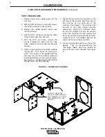
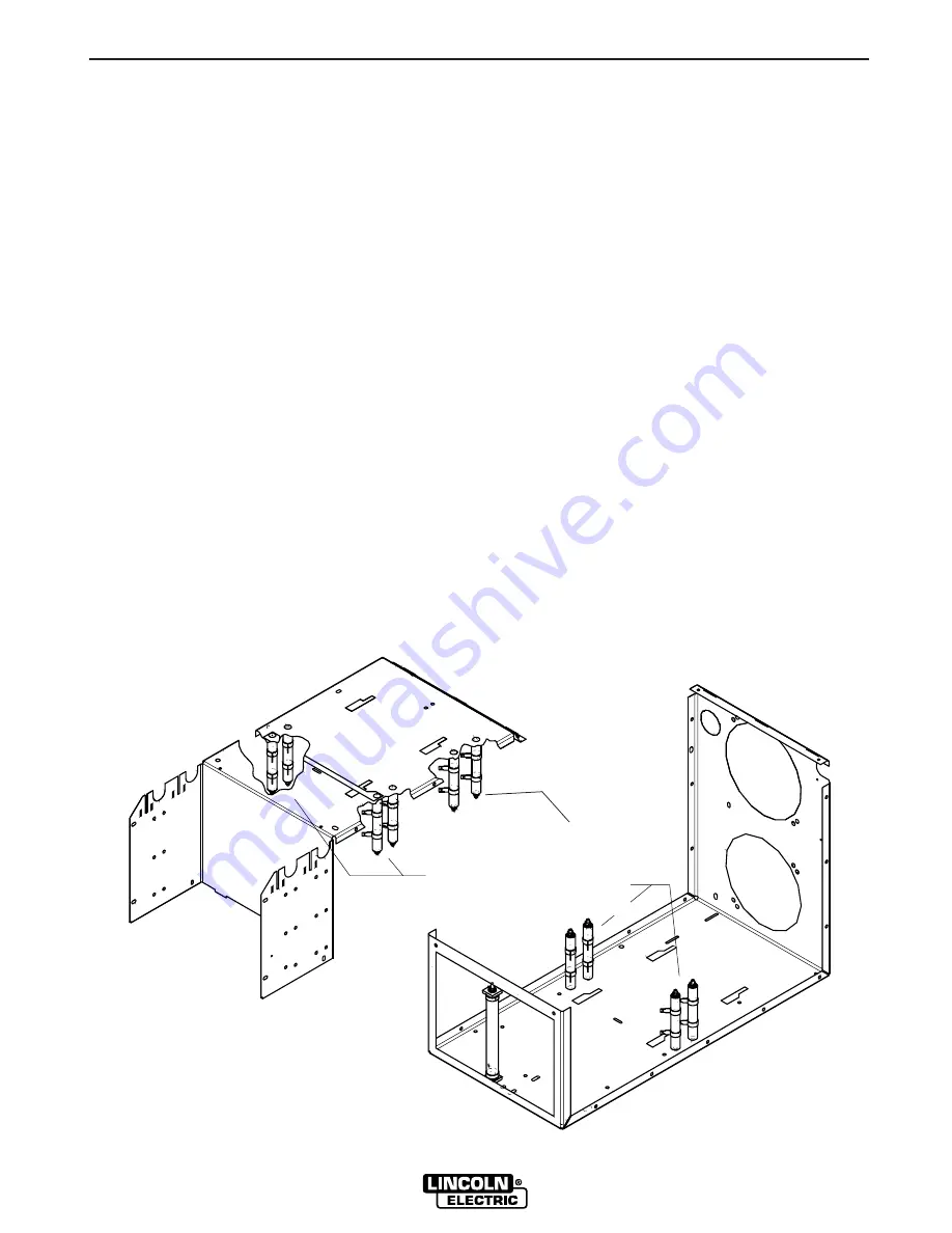
7.  Locate the two sets of two resistors on the

left side of the machine and three sets of
two resistors on the right side of the
machine.  See Figure 1.  Do not touch the
resistors or any other internal machine
component.  Using a DC voltmeter, check
for any DC voltage that may be present
across the terminals of each resistor and
from each resistor to case ground (20 mea-
surements in all).  If a voltage is present, be
careful not to touch these resistors.

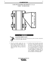
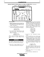
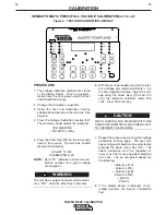
8.  Locate terminals #9 and #12 on the switch

boards.  They can be identified by the
“Discharge” labels, which are located on
each of the four switch boards.  See Figure
2.

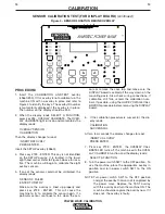
FIGURE 1 – RESISTOR LOCATIONS

5 PAIRS OF RESISTORS
CHECK VOLTAGES BETWEEN
EACH TERMINAL AND FROM
EACH RESISTOR TO CASE
GROUND

Содержание IM573

Страница 1: ... your part DO NOT INSTALL OPERATE OR REPAIR THIS EQUIPMENT WITHOUT READING THIS MANUAL AND THE SAFETY PRECAUTIONS CONTAINED THROUGHOUT And most importantly think before you act and be careful Date of Purchase Serial Number Code Number Model Where Purchased Sales and Service through Subsidiaries and Distributors Worldwide Cleveland Ohio 44117 1199 U S A TEL 216 481 8100 FAX 216 486 1751 WEB SITE ww...

Страница 2: ...nt calibration 25 Robotic Interface P C Board Calibration and Quick Shunt Board Test 29 Robotic Interface Connections 30 Test Procedures After Repair 31 CALIBRATION CAPACITOR DISCHARGE PROCEDURE DISPLAY BOARD REPLACED ROBOTIC PW450 SETUP SEMI AUTOMATIC PW450 SETUP CONTROL BOARD REPLACED DISPLAY SENSOR CALIBRATION CURRENT CALIBRATION CURRENT CALIBRATION QUICK VOLTAGE CALIBRATION IF POSSIBLE FULL VO...

Страница 3: ...instructions on how to properly perform sensor calibration voltage calibra tion and current calibration on Power Wave power sources Additionally a procedure is provided to prop erly discharge the Power Wave s input filter capacitors Electric Shock Can Kill Only qualified personnel should ser vice this equipment Do not touch electrically hot parts Prior to replacing any PC Boards or whenever work i...

Страница 4: ...epartment for electrical trou bleshooting assistance before you proceed Call 1 800 833 9353 WELD PURPOSE FOR THE PROCEDURE This procedure will drain off any charge stored in the four large capacitors that are part of the FET switch board assembly This procedure MUST be performed as a safety precaution before conducting any test or repair procedure that requires you to touch internal compo nents of...

Страница 5: ...iece of insulating material such as a glastic board See Figure 3 NEVER USE A SHORTING STRAP FOR THIS PROCEDURE 7 Locate the two sets of two resistors on the left side of the machine and three sets of two resistors on the right side of the machine See Figure 1 Do not touch the resistors or any other internal machine component Using a DC voltmeter check for any DC voltage that may be present across ...

Страница 6: ...he other jumper lead to the other end of the resistor 10 Carefully connect the needle nose end of one of the jumper leads to terminal 9 See Figure 3 Connect the needle nose end of the other jumper lead to terminal 12 Terminals 9 and 12 are indicated by the Discharge label Leave the resis tor connected for 10 seconds DO NOT TOUCH TERMINALS RESISTORS OR ANY INTERNAL MACHINE COMPO NENTS DURING THIS P...

Страница 7: ... and 12 with the DC voltmeter Terminal 9 has positive polarity and terminal 12 has negative polarity Voltage should be zero If any voltage remains repeat this capaci tor discharge procedure 12 Repeat discharge procedure steps 9 10 and 11 for each of the other three switch boards of the FET switch board assembly POWER WAVE CALIBRATION ...

Страница 8: ...hat WIRE FEEDER 2 LEDs will also change during this procedure 4 Turn the POLARITY LED for WIRE FEEDER 1 back on by again pressing the POLARITY KEY for WIRE FEEDER 1 5 When done properly the LEDs should look as follows Wire Feeder 1 Wire Feeder 2 Polarity LED ON Polarity LED ON Electrode Sense Lead Enabled Electrode Sense Lead Enabled LED ON LED OFF Work Sense Lead Enabled Work Sense Lead Enabled L...

Страница 9: ...bserve all safety notes and precautions detailed throughout this manual If for any reason you do not understand the test procedures or are unable to perform the test repairs safely contact the Lincoln Electric Service Department for electrical trou bleshooting assistance before you proceed Call 1 800 833 9353 WELD TEST DESCRIPTION This procedure recalibrates the eight overlay sensors of the Power ...

Страница 10: ...y 133 ENTER This will cause the machine to try to calibrate the sensor again If a particular sensor continues to fail clean the sen sors or remove the case top and make sure the DISPLAY board is seated all the way down on the mounting posts Also check wiring connections If calibration still fails record the calibration num bers if possible using the QUICK VOLTAGE CALI BRATION procedure before remo...

Страница 11: ...f for any reason you do not understand the test procedures or are unable to perform the test repairs safely contact the Lincoln Electric Service Department for electrical trou bleshooting assistance before you proceed Call 1 800 833 9353 WELD PROCEDURE DESCRIPTION This procedure is a quick way of calibrating the voltage sensing points leads provided that the existing display board is capable of di...

Страница 12: ...gain 5 Repeat the process by pressing the Voltage Calibration function again The next sens ing lead may be selected by pressing the down Arrow Key 101 The above proce dure must be repeated six times to obtain and record the calibration number for six different voltage sensing points These points are the following Polarity 67A Polarity 21A Polarity 67B Polarity 21B Polarity Polarity 6 Install the n...

Страница 13: ...t this manual If for any reason you do not understand the test procedures or are unable to perform the test repairs safely contact the Lincoln Electric Service Department for electrical trou bleshooting assistance before you proceed Call 1 800 833 9353 WELD PROCEDURE DESCRIPTION This procedure is a quick way of calibrating the voltage sensing points leads provided that the existing display board i...

Страница 14: ...and press the Enter Key 133 again 5 Repeat the process by pressing the Voltage Calibration function again The next sens ing lead may be selected by pressing the down Arrow Key 101 The above proce dure must be repeated four times to obtain and record the calibration number for four different voltage sensing points These four points are the following Polarity 67A Polarity 21A Polarity Polarity 6 Ins...

Страница 15: ...LS NEEDED A Test and Calibration Overlay L9660 255 A 300 amp 30 volt resistive grid load A MIG welding load may be used if a grid load is not available Choose an argon rich 30 volt spray procedure See the topic Full Voltage Calibration Using a Welding Arc in this section of the manual A calibrated DC voltmeter accurate to 30 0 volts 0 1 volt A set of jumper leads to access the remote voltage sensi...

Страница 16: ...e voltage only external voltmeter It is the only important reading Adjust the volt age using the Arrow Keys 100 and 101 until the reference voltmeter reads 30 0 volts Press the Enter Key WHEN LOADING THE MACHINE WITH THE CASE PARTS REMOVED BE CAREFUL NOT TO OVERHEAT THE MACHINE 7 Repeat the process by pressing the Voltage Calibration function again The next volt age sensing point lead may be selec...

Страница 17: ... control boards are replaced MATERIALS NEEDED A Test and Calibration Overlay L9660 255 A 300 amp 10 30 volt resistive grid load A MIG welding load may be used if a grid load is not available Choose an argon rich 30 volt spray procedure See the topic Full Voltage Calibration Using a Welding Arc in this section of the manual A calibrated DC voltmeter accurate to 30 0 volts 0 1 volt A set of jumper l...

Страница 18: ...6 With the machine loaded monitor the refer ence voltage only external voltmeter It is the only important reading Adjust the volt age using the Arrow Keys 100 and 101 until the reference voltmeter reads 30 0 volts Press the Enter Key WHEN LOADING THE MACHINE WITH THE CASE PARTS REMOVED BE CAREFUL NOT TO OVERHEAT THE MACHINE 7 Repeat the process by pressing the Voltage Calibration function again Th...

Страница 19: ...ssistance before you proceed Call 1 800 833 9353 WELD PROCEDURE DESCRIPTION This procedure is necessary if the display board is replaced and the Quick Voltage Calibration or the Normal Full Voltage Calibration is NOT possible MATERIALS NEEDED A Test and Calibration overlay L9660 255 the test procedure can be done without this A Synergic 7 wire feeder A calibrated DC voltmeter accurate to 0 1 volts...

Страница 20: ...r a given voltage sense point The machine s output terminals will be electri cally HOT when the Enter Key is pressed 6 Adjust the wire feed speed on the Synergic 7 to 500 IPM some wire feed speed to get into the spray range NOTE When the Enter Key is pressed it will clear the wire feed speed to 200 IPM The wire feed speed must be adjusted after pressing the Enter Key but before starting to weld 7 ...

Страница 21: ...or block of the wire feeder to the positive output terminal on the front of the machine 9 Turn the machine off Connect the Synergic 7 to the Wire feeder 2 amphenol on the back of the Power Wave machine 10 Put the voltmeter sense lead back on the wire feeder conductor block and repeat the calibration process steps 5 6 and 7 for the following test points POLARITY 67B POLARITY 21B NOTE Do not attempt...

Страница 22: ...nce before you proceed Call 1 800 833 9353 WELD PROCEDURE DESCRIPTION This procedure is necessary if the control and or the shunt amplifier boards are replaced The current control is the most critical function in the Power Wave machine MATERIALS NEEDED Test and Calibration Overlay L9660 255 A 300 amp 30 volt resistance grid load A small trimmer screwdriver A calibrated DC ammeter accurate to read ...

Страница 23: ... VOLTAGE POINTS ARE EXPOSED STAND DIRECTLY IN FRONT OF MACHINE UNDER TEST EXPLODING PARTS CAN CAUSE INJURY FAILED PARTS CAN EXPLODE OR CAUSE OTHER PARTS TO EXPLODE WHEN POWER IS APPLIED ALWAYS WEAR A FACE SHIELD AND LONG SLEEVES WHEN SERVICING WHEN LOADING THE MACHINE WITH THE CASE PARTS REMOVED BE CAREFUL NOT TO OVER HEAT THE MACHINE 3 NOTE If a wire feeder is NOT connected to the Power Wave the ...

Страница 24: ...e the external trigger device K941 1 and load the machine The machine s output terminals will be electri cally HOT when the trigger circuit is activated 5 Adjust the potentiometer until the reference external ammeter reads 304 amps 1 0 amps The load voltage should be greater than 15 volts but less than 35 volts 6 Remove power to the machine 7 If necessary re install the control board 8 Replace the...

Страница 25: ...Lincoln Electric Service Department for electrical trou bleshooting assistance before you proceed Call 1 800 833 9353 WELD PROCEDURE DESCRIPTION This procedure is necessary if the control and or the shunt amplifier boards are replaced The current control is the most critical function in the Power Wave machine MATERIALS NEEDED Test and Calibration Overlay L9660 255 A 300 amp 30 volt resistance grid...

Страница 26: ...CASE IS REMOVED HIGH VOLTAGE POINTS ARE EXPOSED STAND DIRECTLY IN FRONT OF MACHINE UNDER TEST EXPLODING PARTS CAN CAUSE INJURY FAILED PARTS CAN EXPLODE OR CAUSE OTHER PARTS TO EXPLODE WHEN POWER IS APPLIED ALWAYS WEAR A FACE SHIELD AND LONG SLEEVES WHEN SERVICING WHEN LOADING THE MACHINE WITH THE CASE PARTS REMOVED BE CAREFUL NOT TO OVER HEAT THE MACHINE 3 NOTE If a wire feeder is NOT connected to...

Страница 27: ...r the PW450 and apply the load See EXTERNAL TRIGGERING CIRCUIT on the next page The machine s output terminals will be electri cally HOT when the trigger circuit is activated 5 Adjust the potentiometer until the reference external ammeter reads 304 amps 1 0 amps The load voltage should be greater than 15 volts but less than 35 volts 6 Remove power to the machine 7 If necessary re install the contr...

Страница 28: ... interface board See the following table and figure 3 When the 24VDC supply is correctly wired in place and turned on the welding output terminals can be energized by closing the switch CALIBRATION 28 28 POWER WAVE CALIBRATION EXTERNAL TRIGGERING CIRCUIT Voltage Switch Signal P82 Connector Pins Interface Board Connectors 24VDC 100ma P82 r J106 3 Wire 534 P82 a J106 4 Wire 535 Normally open switch ...

Страница 29: ...ition until you are sure that you are just at the point of change from high voltage to low 2 Remove the positive probe from the J109 pin 2 position and attach it to lead nine of X 12 Leave the nega tive lead at J109 pin 4 The voltmeter should now be reading less than one volt Example 0 345 MV 3 Slowly continue to adjust the trimmer clockwise until the voltage reading has increased 100 MV 0 100 vol...

Страница 30: ...106 6 Spare robot output P82 Z WDO8 J106 7 Gas shortage input P84 A J106 8 Gas shortage GND P84 B J103 1 42VDC Full wave bridge J103 2 42VDC Full wave bridge J103 3 Touch 2 4 output 2 PROT J34 4 J103 4 Touch 2 4 output 4 PROT J34 7 J103 5 Tach PWR P83 G J103 6 Tach signal P83 F J103 7 Tach GND P83 H J103 8 Motor P83 A J103 9 Motor P83 B J103 10 Weld 2 4 output 2 PROT J34 11 J103 11 Weld 2 4 output...

Страница 31: ...component side of the Interface board and with the power on observe a flashing LED on the Interface board If LED is not flashing replace Interface board 3 Disconnect the power and measure the resistance from P83 feeder connector pin F to J103 pin 6 at the Interface board connector P83 feeder connector pin G to J103 pin 5 at the Interface board connector P83 feeder connector pin H to J103 pin 7 at ...

Страница 32: ...s and Service through Subsidiaries and Distributors Worldwide Cleveland Ohio 44117 1199 U S A TEL 216 481 8100 FAX 216 486 1751 WEB SITE www lincolnelectric com World s Leader in Welding and Cutting Products ...

Отзывы: