background image

A-49

OPERATION

APEX

®

 3 SERIES TIG PENDANT MANUAL

Copy to/from USB

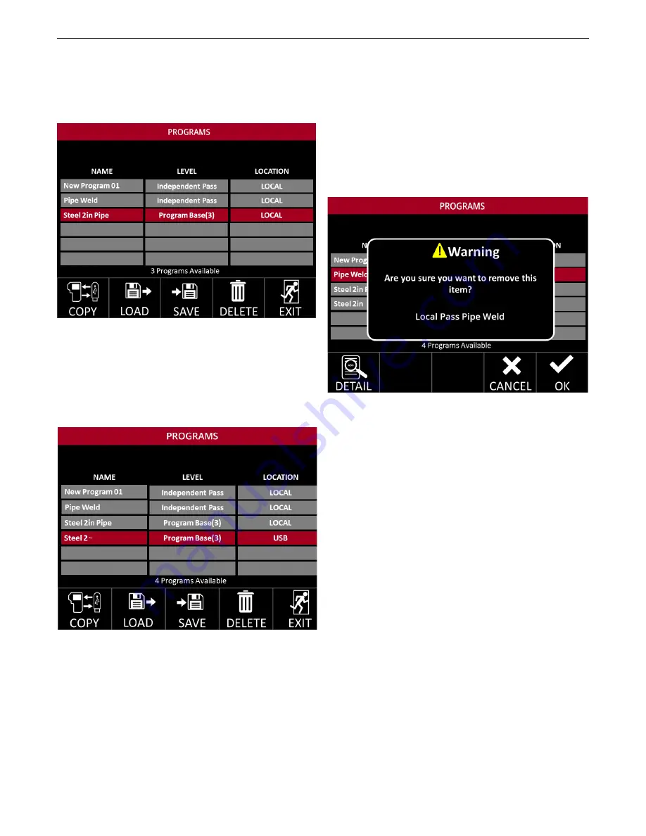
With the USB inserted, a Copy Icon appears in the 
bottom left of the screen - see 

FIGURE 48 - Copy 

Icon.

Press the Copy Selection Button. A copy of the selected 
program is made – see 

FIGURE 49 - Copy to USB

If the file is currently saved on the USB, it will save to 
the Pendant, if it is a Local file (saved to the Pendant),  
it will save to USB.

Note: If a locally saved program has more than 8 
characters (including spaces), copying to a USB will 
truncate it to the first 8 characters of the original name, 
as shown in 

FIGURE 48 - Copy to USB.

 To save with 

a unique name, load the program and then manually 
save to the USB with the desired 8-character name.

Deleting a Program

Saved programs can be deleted by highlighting the 
program and pressing the Delete Selection button. 
This will bring up a new window – see 

FIGURE 50 - 

Program Delete

. Press the Delete Selection Butto

Deleting a Program Base

If a Program Base is deleted then all associated 
passes are also deleted.

FIGURE 50 - Program Delete

FIGURE 49 - Copy to USB

FIGURE 48 - Copy Icon

Содержание APEX 3 Series

Страница 1: ...s 12880 Need Help Call 1 888 935 3877 to talk to a Service Representative Hours of Operation 8 00 AM to 6 00 PM ET Mon thru Fri After hours Use Ask the Experts at lincolnelectric com A Lincoln Service Representative will contact you no later than the following business day For Service outside the USA Email globalservice lincolnelectric com Save for future reference Date Purchased Code ex 10859 Ser...

Страница 2: ...athing zone and the general area IN A LARGE ROOM OR OUTDOORS natural ventilation may be adequate if you keep your head out of the fumes See below USE NATURAL DRAFTS or fans to keep the fumes away from your face If you develop unusual symptoms see your supervisor Perhaps the welding atmosphere and ventilation system should be checked WEAR CORRECT EYE EAR BODY PROTECTION PROTECT your eyes and face w...

Страница 3: ...lled fuel from vaporizing on contact with hot engine parts and igniting Do not spill fuel when filling tank If fuel is spilled wipe it up and do not start engine until fumes have been eliminated 1 d Keep all equipment safety guards covers and devices in position and in good repair Keep hands hair clothing and tools away from V belts gears fans and all other moving parts when starting operating or ...

Страница 4: ...g Headshield and filter lens should conform to ANSI Z87 I standards 4 b Use suitable clothing made from durable flame resistant material to protect your skin and that of your helpers from the arc rays 4 c Protect other nearby personnel with suitable non flammable screening and or warn them not to watch the arc nor expose themselves to the arc rays or to hot spatter or metal FUMES AND GASES CAN BE ...

Страница 5: ...crease the possibility of the welding current passing through lifting chains crane cables or other alternate circuits This can create fire hazards or overheat lifting chains or cables until they fail 6 h Also see item 1 c 6 I Read and follow NFPA 51B Standard for Fire Prevention During Welding Cutting and Other Hot Work available from NFPA 1 Batterymarch Park PO box 9101 Quincy MA 022690 9101 6 j ...

Страница 6: ...ed in the environment is compatible This may require additional protection measures h the time of day that welding or other activities are to be carried out The size of the surrounding area to be considered will depend on the structure of the building and other activities that are taking place The surrounding area may extend beyond the boundaries of the premises METHODS OF REDUCING EMISSIONS Mains...

Страница 7: ...7 SAFETY APEX 3 SERIES TIG PENDANT MANUAL ...

Страница 8: ...Screen A 21 Test Screen Buttons A 21 Weld Screen A 22 Weld Screen Buttons A 22 Jog Screen A 22 Jog Buttons A 23 Oscillation Screen A 24 Oscillation Buttons A 25 Setup Screen A 26 Setup Screen Options A 26 Track Setup A 27 Track Type A 27 Track Ring Size A 27 Pipe Size A 27 Heavy Wall Pipes A 27 Travel Setup Screen A 28 Process Setup Screen A 29 Standard Process Options A 29 Weave Process Options A...

Страница 9: ...nt A 45 Saving an Independent Pass A 45 Saving a Program Base A 46 Saving a Program Pass A 46 Saving Program Updates A 47 Hide Program Passes A 48 Saving to a USB A 48 Copy to from USB A 48 Deleting a Program A 49 Deleting a Program Base A 49 Loading a Program A 49 Overwriting a Program A 50 Operator Navigation Chart A 51 Diagrams G 52 Standard Piping Schedule Chart G 54 Parts Manual G 55 ...

Страница 10: ... Travel Travel Setup Speed Left Dwell Settings Service Page Swap Shift Case Width Right Dwell Increment Unit Settings Gas Advanced Settings Next Index Travel Direction Positioner ID Track Wire Feed Forward Travel Direction Wire Wire Feed Speed OD Track Steering Oscillator Wire Speed Reverse Travel Direction Previous Index Flat Track Wire Diam eter Travel Direction Add User Direction Delay Volts Pe...

Страница 11: ...he pendant should be kept dry and sheltered from rain and snow Do not place or drop the pendant on wet ground or in puddles Always place the pendant on a sturdy flat level surface when not in use and be sure to unplug it Operation Read this entire process and operations manual before using the pendant Keep hands away from weld head wire feeder and other moving parts while in operation CAUTION Neve...

Страница 12: ...kwise See FIGURE 1 APEX Pendant Reset Button This reset button can be used to restart the system for troubleshooting purposes and to halt welding and system movement Startup Screen When the system is reset at the Power Wave the screen will display Checking Network Connection Calibrating System FIGURE 2 Startup Screen This is a normal part of the initialization process Note During the start up inte...

Страница 13: ...effects exhibited will continue or speed up Example When pressing button 1 in the jog screen gas will purge for 3 seconds Holding down button 1 will cause the gas to continuously purge 4 HOLD AND ROTATE The steering knob also acts as a button It can be pressed or rotated for differ ent actions for some screens It can be held down and rotated for faster navigation Selection Buttons Buttons 1 throug...

Страница 14: ...n menu screens 13 START STOP Short Press Start if idle stop if welding stop start test weld when in test mode 14 SECTOR Short Press Switches between sectors if avail able switches between passes if available on the Increments screen turns Auto Sector feature ON OFF on the Sectors Screen 15 RESET Short Press stops the welding sequence and all motion Twist Release IMPORTANT The reset button is not a...

Страница 15: ...s a four digit log code in to log in Use the left toggle to change from one variable to the next Use the right toggle to change the selected variable Press the Enter selection button when user code has been entered Once a four digit code is accepted the system automatically moves into the default Idle screen see FIGURE 6 Idle Screen Default This screen is shown when a supervisor logs into the syst...

Страница 16: ...OGGLE White Border Short Press Pressing up or down moves cursor between spaces 7 STEERING KNOB Fast Movement 8 RIGHT TOGGLE Gray Border Short Press Pressing up or down changes value of the selection 9 WIRE FEED AMPS No Effect 10 DWELL No Effect 11 OSCILLATION No Effect 12 TRAVEL VOLTS No Effect 13 START STOP No Effect 14 SECTOR No Effect 15 RESET Short Press stops the welding sequence and all moti...

Страница 17: ... Idle Screen Wire Feed Speed Peak value Wire Feed Speed Background value Amps Peak value Amps Background value Hot Wire Amps Peak value Hot Wire Amps Background value Dwell Left value Dwell Right value Oscillation Speed value Oscillation Width value Travel Speed value Voltage Peak value Voltage Background value Pressing the different menu buttons will change the displayed values which correspond t...

Страница 18: ...utton again If Wire Feed Speed and Hot Wire Amp Background values are included in the weld variable configuration the Idle Screen shows the Wire Feed and Hot Wire Amps Background values Continuing to push the Wire Feed Speed Amps but ton will cycle through displays of all the available Wire Feed Speed Amps and Hot Wire Amps values Pressing this menu button will open the Dwell Menu button options P...

Страница 19: ...he Setup Screen 3 PASS Short Press Switches to the next pass in the weld program if available 4 WIRE FEED Short Press Enables or disables wire feeding 5 TEST WELD Short Press Switches between weld and test modes FIGURE 8 shows system in Weld Mode 6 LEFT TOGGLE White Border Short Press Changes the value displayed in the top left box In the example FIGURE 8 Idle Screen Default the value will change ...

Страница 20: ... emergency stop button Power is still being applied to the system Idle Screen Test Weld Modes After preparing a program it is recommended that the user test the parameters before striking an arc The system allows for a test mode of all non weld functions such as travel gas purge flow oscillation and others Pressing the Weld Test Selection button will change the system from Test to Weld mode The ic...

Страница 21: ...ion of the oscillation axis 6 Torch Height Displays the relative location of the height axis The screen shot above FIGURE 9 Static Items illustrates the icons that appear o the weld screen These icons are for information only and are not select able variables Test Screen Similar to the Weld screen the Test Screen will show voltage and amperage feedback but the feedback values will be zero see FIGU...

Страница 22: ... page 20 Pressing the Start Stop button during the weld halts the weld and moves into the Jog Menu Jog Screen The Jog Screen is used to test movement of the system before welding The Jog Screen can be entered from the Idle or Oscillation screens From the Idle Screen see FIGURE 14 Idle Screen press and hold the Wire Feed Amps or the Travel Volt age menu buttons to enter the Jog Menu The FIGURE 15 J...

Страница 23: ...Idle Screen 6 LEFT TOGGLE White Border Short Press Travels forward or backward slightly Hold Ramps travel speed 7 STEERING KNOB Rotate Moves the oscillation in and out Short Press Centers the oscillation Long Press Starts stops oscillation test 8 RIGHT TOGGLE GRAY BORDER Short Press Adjusts the torch up and down Hold Ramps adjustment speed 9 WIRE FEED AMPS No Effect 10 DWELL Short Press Navigates ...

Страница 24: ... Dwell Menu Button will present the user with the option to change the left and right dwells In either screen use a short press to switch between Oscillation and Dwell The items highlighted in red are the variables that can be changed Press the SWAP selection button to be taken to the Travel Setup Screen Travel Setup is discussed in the Travel Setup Screen section on page A 28 This screen allows t...

Страница 25: ...cillation in and out Short Press Centers the oscillation Long Press Starts stops oscillation test 8 RIGHT TOGGLE Gray Border Short Press Increases or decreases Right Dwell time or Oscillation Speed Hold Increases or decreases value continuously 9 WIRE FEED AMPS Short Press Navigates to Jog Menu 10 DWELL Short Press Switches to Dwell option when in Oscillation option otherwise no effect 11 OSCILLAT...

Страница 26: ...etup Screen Options Track Setup selects from internal or external track flat track and the size of the pipe where applicable Travel Setup change the steering controls based on where the operator is standing in relation to the track and set up the weave pattern Process Setup sets up the weld process Start Settings adjustment specific to the programs affecting how the system will react when the weld...

Страница 27: ...ressing and holding the right toggle will in crease the speed at which the values change Use the nominal sizes for the track rings THESE NOMINAL SIZES ARE STAMPED INTO THE TRACK Pipe Size The third field that can be changed is the pipe size This can range from 4 inches to 100 inches The value can be adjusted in increments of 0 01 inches Holding the right toggle for longer than 2 seconds will ampli...

Страница 28: ...on the track Setting the orientation and travel direction allows for intuitive operation With the travel field highlighted the weld head orienta tion and travel direction can be selected There are four different options available All directions refer to the weld head and are in relation to the users view facing the weld head 1 Facing Right Traveling Down 2 Facing Left Traveling Down 3 Facing Right...

Страница 29: ...mperage Indicates the welding amperage Can have both a Peak and Background value when Pulsed Welding is selected Hot Wire Amperage amperage applied to the wire when the Hot Wire feature is enabled Can have both a Peak and Background value when Pulsed Welding is selected Access to this vari able is provided only when Hot Wire equipment is available The four process options that can have both a Peak...

Страница 30: ...lation excursion and dwells When either step Travel or Continuous Travel is selected as the weave value additional Oscillation Settings become available Oscillation Settings include the following Oscillation Method Oscillation can be Physical Oscillation where the oscillator physically moves the torch or Magnetic Oscillation where the arc is manipulated magnetically Oscillation Width Determines th...

Страница 31: ...as the current weld mode Advanced Process Setup Certain weld modes have advanced settings specific to that mode or process Pressing the ADV Selection button on the Process Setup screen will present the user with the advanced options associated with the selected weld mode see FIGURE 22 and FIGURE 23 Advanced Process Setup and Advanced Process with Hot Wire When Hot Wire equipment is available and H...

Страница 32: ...FIGURES A and B Maintaining a low height sensitivity allows for higher quality and more consistent welds This includes ad justing for out of round pipes maintaining heat input and helping with puddle control on the joint profile It is recommended that the operator start the weld at a lower sensitivity setting for the best performance This will also assist in avoiding an over reaction to changes in...

Страница 33: ...Options means that none of the four synchronized weld variables will alternate between Peak and Background output levels Instead it will maintain the same output level throughout the weld With the choice of either Sync to Oscillation or Sync to Pulse the user is allowed to choose which of the synchronization variables will alternate between the Peak and Background output levels and set the paramet...

Страница 34: ...ue associated with Voltage can take one of three values as shown in FIGURE 26 Voltage Sync Values Selecting the Peak Only option means that the Peak voltage value will be output at all times when welding Selecting the Background Only option means that the Background voltage value will be output at all times when welding Selecting the Peak and Background option means that the voltage output while w...

Страница 35: ... screen displays a representation of a cross section of a horizontally positioned pipe with sector markers place on the pipe perimeter showing the position of the sector transi tion point for each enabled sector in the weld process based on the travel direction On the left side of the screen the same information is displayed numerically in a table In the middle of the screen at the top the current...

Страница 36: ...values at the 140 mark and unless stopped by the user would wrap around to repeat the Sector 1 parameter values at the 5 mark The Auto Sector feature does not currently provide the option to automatically stop the weld The user of course can stop the weld at any point during the auto sector process When a test or weld starts with the auto sector feature enabled the progress of the weld with respec...

Страница 37: ...t Settings screen the symbol next to the sector icon is an S rather than a sector number End Settings The end settings screen see FIGURE 30 End Set tings Screen allows the user to adjust the end set tings specific to the program which affect how the system will behave at the end of the weld End settings begin to take effect as soon as the Start Stop button is pressed to stop the weld Refer to page...

Страница 38: ... Service Motion items are Steering Increment Allows the supervisor to set the distance the oscillation will move for each click of the steering knob Head Orientation To change the torch orientation relative to the weld head the supervisor must also change the system settings in addition to physically inverting the weld head Torch Retract Distance Change how far the torch retracts at the end of the...

Страница 39: ...nd then the Right Toggle to turn monitoring ON OFF With gas monitoring turned ON two additional controls are made available a LEVEL selection to input the re quired level of gas flow using the Right Toggle and a REF value which will display the current gas flow value when the PURGE button is pushed With the Water Fault turned ON the water flow will be monitored during welding If it s determined th...

Страница 40: ...d into the APEX 30M APEX 30S or APEX 3000 the Pendant will allow a snapshot to be taken from the screens shown in FIGURE 31 FIGURE 32 and FIGURE 38 A snapshot provides detailed information concerning the systems current configuration and the status and is initiated by pushing the SNAP Selection button The snapshot process may take several minutes to complete during which time a status screen like ...

Страница 41: ...th supervisor access are able to view the users screen Press the Add User Selection button As demonstrated in FIGURE 41 Add User pressing the Add Selection button will bring up the Add User screen Note Toggle switches do not work on the Add User Screen only the steering knob Once the code has been selected the supervisor can determine the user s level of access Operator The operator has no access ...

Страница 42: ...e view what is being deleted The warning screen shows the level of access and the user code In this instance it is USER 0008 If this User Code had Supervisory ac cess the screen would read SUPERVISOR 0008 If there are too many users to fit on the screen the last box will contain ellipses see FIGURE 42 Multiple Users This indicates that there are additional system users At the bottom of the fields ...

Страница 43: ...limit the operator s access to certain parameters The minimum and maximum values provided to the user are based on welding power source weld mode and other items The increments options that can be set are Wire Feed Speed Voltage or Trim depending on the weld mode Amperage Travel Speed Oscillation Width Oscillation Speed Dwell Time Each of these values can have a minimum and maxi mum value set that...

Страница 44: ...eed ipm cm min Runin Voltage Volts Volts Motion Delay seconds seconds END SETTINGS MENU Crater Wire Feed Speed ipm cm min Crater Voltage Volts Volts Crater Time seconds seconds Burnback seconds seconds Downslope seconds seconds Postflow seconds seconds PROCESS SETUP MENU Wire Feed Speed ipm cm in Voltage Volts Volts Amperage Amps Amps Travel Speed ipm cm min Oscillation Width inches centimeters Os...

Страница 45: ... Level Selects what type of Program is being saved Independent Pass stand alone weld procedures not tied to any other program Program Base The first step in creating multiple passes which tie together to form a full welding procedure this is explained in the next section Program Pass These are tied to the Program Base and can be created as needed by the user For example a pipe could require four p...

Страница 46: ...se If there are multiple passes on the same material setting up a Program Base is recommended In the save program sub menu change the level from Independent Pass to Program Base Saving a Program Pass Once a program base is saved the next step is to create individual passes within the Program Base for the settings to be saved ...

Страница 47: ...ave been made to one or more Pro gram Passes and the Program Base containing the changed Program Passes is selected and the SAVE button is pressed the Program Update option becomes available on the SAVE screen If changes were made to one or all of the Program Passes associated with the Program Base Steel 2in Pipe selecting the Program Base and pressing the SAVE button would product the following s...

Страница 48: ...y can also be saved to a USB The USB has a folder set up specifically to save or read files If this folder is missing then a prompt will appear on the screen see FIGURE 47 USB Folder Notification If the flash drive is new the system will create a folder once the pendant operator presses Ok To access files already saved on the USB move them to the specified directory Note A USB file name is restric...

Страница 49: ...than 8 characters including spaces copying to a USB will truncate it to the first 8 characters of the original name as shown in FIGURE 48 Copy to USB To save with a unique name load the program and then manually save to the USB with the desired 8 character name Deleting a Program Saved programs can be deleted by highlighting the program and pressing the Delete Selection button This will bring up a...

Страница 50: ...ion button This will load the ap plicable program See FIGURE 51 Loading Program and FIGURE 52 Loaded Program Overwriting a Program Saving a file with the same name will overwrite the existing program The system gives a warning that the existing program will be overwritten Overwriting it will delete the original program FIGURE 51 Loading Program FIGURE 52 Loaded Program ...

Страница 51: ... Selection button 4 Move into Active Test to verify all weld settings or Active Weld to begin welding 5 From the Idle Screen long pressing the menu buttons will take the operator to the corresponding Jog or Oscillation Menu Use the menu buttons to switch between the two menus 6 It may be necessary to change the weld head orientation This allows the user to set how the weld head steers and operates...

Страница 52: ...TION UNITS SCALE ARC PRODUCTS DRAWN BY ENGINEER CONTROL THIS DOCUMENT CONTAINS PROPRIETARY INFORMATION OWNED BY LINCOLN GLOBAL INC AND MAY NOT BE DUPLICATED COMMUNICATED TO OTHER PARTIES OR USED FOR ANY PURPOSE WITHOUT THE EXPRESS WRITTEN PERMISSION OF LINCOLN GLOBAL INC PROPRIETARY CONFIDENTIAL A INCH J SNEAD 6 1 18 APPROVAL DATE 1 OF 1 S32569 PENDANT WIRING DIAGRAM J SNEAD SC S30454 PENDANT IF P...

Страница 53: ...l Torch Height Up Down Off Start Gap Torch Up AVC Start Travel Off Voltage Background Peak 0 Amperage Upslope Background Peak Start Amps Preflow Final Amps Pulses Per Second Peak Time 0 Gas Off On Tungsten Preheat Start Stop Button Pressed Postflow Sync to Oscillation Sync to Oscillation Pulses Per Second Pulses Per Second Sync to Oscillation Travel Start Step Travel Continuous Travel GTAW Timing ...

Страница 54: ...62 7 161 5 154 1 146 3 139 7 136 7 124 4 8 8 625 219 1 5S 10S 20 30 40ST 40S 60 80SX 80S 100 120 140 XX 160 0 109 0 148 0 25 0 277 0 322 0 406 0 5 0 594 0 719 0 812 0 875 0 906 2 77 3 76 6 35 7 04 8 18 10 31 12 7 15 09 18 26 20 62 22 23 23 01 8 407 8 329 8 125 8 071 7 981 7 813 7 625 7 437 7 187 7 001 6 875 6 813 213 5 211 6 206 4 205 202 7 198 5 193 7 188 9 182 5 177 8 174 6 173 1 OD in OD mm Sch...

Страница 55: ...G 55 PARTS GENERAL ASSEMBLY APEX 3 SERIES TIG PENDANT MANUAL APEX 3 SERIES TIG PENDANT PARTS Code 12834 This parts list is provided as an informative guide only ...

Страница 56: ... Parts List for a machine if its code number is not listed Contact the Service Department for Use the illustration of Sub Assemblies page and the table below to determine which sub assembly page and column the desired part is located on for your particular code machine Sub Assembly Item Number 1 2 3 4 5 6 7 APEX 3 Series Pendant SUB ASSEMBLY PAGE NAME PAGE NO CODE NO 12834 1 APEX 3 Series TIG Pend...

Страница 57: ...G 57 PARTS NOTE This Parts Manual is provided as an informative guide only when ordering parts always refer to the Lincoln Electric Parts List GENERAL ASSEMBLY 12 31 18 APEX 3 SERIES TIG PENDANT MANUAL ...

Страница 58: ...itch PCB Harness 9SS30717 1 X 12 12A 12B Pendant Input Harness Assembly includes Pendant Input Harness Screw 9SS30458 NSS NSS 1 1 4 X X X 13 13A 13B I O PCB Assembly includes I O PCB Screw 9SS31339 NSS NSS 1 1 7 X X X 14 14A 14B User Interface PCB Assembly includes User Interface PCB Screw 9SS31337 NSS NSS 1 1 7 X X X 15 15A 15B 15C Pendant Hook Assembly includes Pendant Hook Rubber Bumper Screw 9...

Страница 59: ...stomer s particular purpose with respect to such information or advice As a matter of practical consideration we also cannot assume any responsibility for updating or correcting any such information or advice once it has been given nor does the provision of information or advice create expand or alter any warranty with respect to the sale of our products Lincoln Electric is a responsive manufactur...

Страница 60: ...stomer s particular purpose with respect to such information or advice As a matter of practical consideration we also cannot assume any responsibility for updating or correcting any such information or advice once it has been given nor does the provision of information or advice create expand or alter any warranty with respect to the sale of our products Lincoln Electric is a responsive manufactur...

Отзывы: