5
LINCE ITALIA S.p.A.
2. INSTALLATION
For wall installation, do as follow:
•
open the lid by pressing lightly on the side as shown in the figure;
•
pass the BUS cable (
fig. 1 D
) through the precut
G
on the bottom;
•
fix the bottom on the wall using the fixing wall
H
on the bottom;
•
connect the BUS cable to the system bearing in mind the meaning of the three colours of the cable;
•
red: power 12 Vdc;
•
black: ground;
•
white: BUS;
•
connect the
D
connector placed on the board.
2.1 FIRST POWER ON
As soon as the keyboard is connected to the BUS, you will be asked to calibrate the display following the information on the screen
and then the next screen will be displayed:
Proceed with storing the keypad on the control panel, referring to the manual on the GOLD control panel in the section related to the
storing of BUS peripherals.
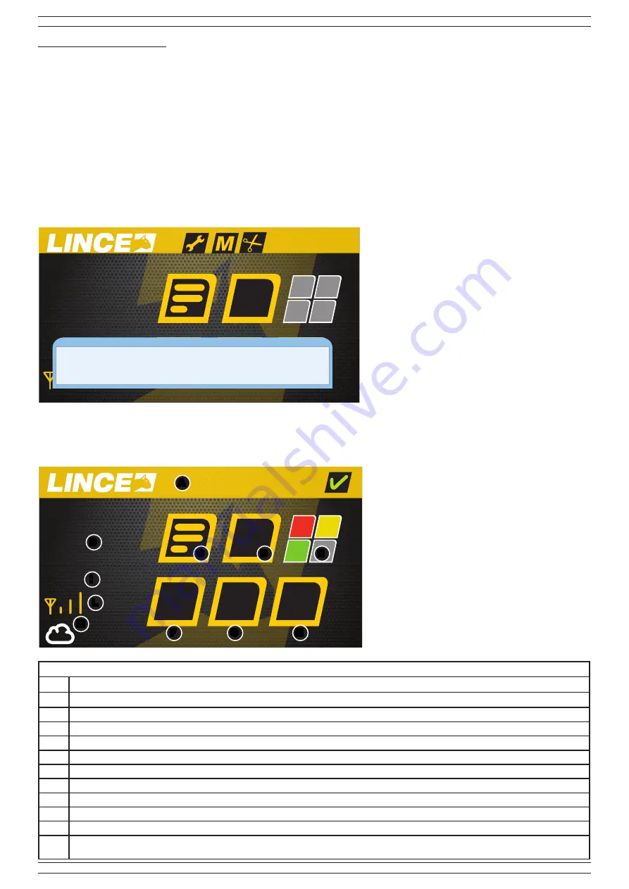
2.2 DEFAULT SCREEN DESCRIPTION
Table 4
Part.
Identification
A
Status bar
B
Time and date
C
Key for access to the menu (access with code)
D
Key for quick total disarming (access with code)
E
Icons for displaying the system status of arming/disarming (red program 1, yellow program 2, green program 3)
F
Preferred key 1 freely associated with combinations of programs or super-keys
G
Preferred key 2 freely associated with combinations of programs or super-keys
H
Preferred key 3 freely associated with combinations of programs or super-keys
I
Room temperature
L
GSM signal level indication
M
The cloud symbol is displayed only if the control panel is connected to the LINCE Cloud. Close to it, the connection mode is displayed if in GPRS
(as in the example) or in WIFI
Fig. 3
00:00
01/01/2005
20°
D
P1 P2 P3
NOTE:
if the BUS is occupied by another keyboard
or by the keyboard of the control panel, the
message “BUS busy with another device”
will be displayed.
16:29
21/10/2015
20°
D
P1 P2 P3
Fig. 4
A
B
C
D
E
F
G
H
I
L
M
Info
Verify devices communications on BUS
GPRS


