background image

IS517 ECN4508 

Page 9  

TERMINAL
LID

TERMINAL
BRACKET

EARTH
TERMINALS

FRAME HEATERS
TERMINAL BLOCK

LIGHT TERMINAL
BLOCK

INSTALLATION INSTRUCTIONS FOR C6R/75U, C6R/100U, 
C6R/125U DROP-IN MODELS 

Refer to the information on page 4 before proceeding. 
 
The cabinet is not connected to the refrigeration module during transit. Remove 
the doors, shelves and base panels from the cabinet and lift this from the pallet 
first to separate the two parts of the appliance. 
Prepare the counter taking note of the ventilation requirements on page 11. 
Cut a hole in the counter top according to the diagram (2) on page 10. Lift the 
refrigeration module onto the counter top so that the electrical supply cable is 
on the customer

’s side.  Lower through the hole and ensure that the cable is not 

trapped.   
Carefully lower the cabinet over the refrigeration module and onto the counter 
top ensuring the cables are not trapped. The plinth around the base of the  
cabinet must be fully supported by the counter top beneath; no part of this plinth 
should be allowed to overhang the counter top. 
Open the evaporator box back lid, connect cables to terminal blocks (see 
diagram below) 

BROWN FROM

TERMINAL

BLUE FROM

TERMINAL

CH 1

CH 2

EARTH

WIRES

CABINET

EARTH

BROWN TO

LIGHT

BLUE TO

LIGHT

BROWN FROM

LIGHT SWITCH

BLUE FROM

LIGHT SWITCH


Using the screw supplied secure 
the terminal lid and hinged lid. 
Replace base panels, shelves 
and doors. 


The cabinet is now ready for use 
Refer to operating instruction on 
page 19.  


Содержание C6R/100U

Страница 1: ...IS517 ECN4508 Page 1 User and Installation Instructions C6R 75U C6R 100U C6R 125U C6R 105 C6R 130 D6R 75 D6R 100 D6R 125 D5R 100 D5R 125 D3R 100 Seal Refrigerated Merchandisers ...

Страница 2: ...f before making any electrical repairs To minimise shock and fire hazards please do not plug or unplug the unit with wet hands During maintenance and cleaning please unplug the unit where required Care must be taken when handling or working on the unit as sharp edges may cause personal injury we recommend the wearing of suitable PPE Ensure the correct moving and lifting procedures are used when re...

Страница 3: ...lation Instruction for C6R U 9 Details of C6R U cabinets 10 Details of cut out for refrigeration module 11 Ventilation requirement for counter top models 12 Wiring Diagrams 13 14 15 Troubleshooting 16 17 18 Operating instructions 19 Cabinet Controls 19 Loading 19 Cleaning and maintenance 20 Cleaning the condenser 20 Replacing the light 20 Service information 21 Conditions of guarantee 21 USE OF TH...

Страница 4: ...st of hygiene you should clean the product after unpacking and ensure all plastic coatings are removed before use This unit is heavy Be aware of the risks when lifting or moving it Always lift the cabinet using the base or lower frame do not lift with any other part Do not pull the unit across your work surface as it may make a mark The cabinet relies on the circulation of cold air which must pass...

Страница 5: ...ing Temperature O C 25 Internal volume litres 245 0 332 0 242 0 368 0 322 0 Internal dims cm 710x570x560 960x570x560 710x570x560 1210x570x560 960x570x560 Width mm 750 1000 1050 1250 1300 Depth mm 650 650 650 650 650 Height mm 755 755 755 755 755 Power Rating watt 602 717 604 729 717 Weight kg 89 5 117 105 137 5 112 2 Refrigerant R452a Model D3R 100 D5R 100 D5R 125 D6R 75 D6R 100 D6R 125 Max Operat...

Страница 6: ...igeration module D5R 100 D5R 125 D3R 100 Models As above except 1 x chrome plated shelf and removable base plate Model Components Compressor Light Controller Evaporator fan Condenser Fan Motor Shelf D3R 100 CR08 LA01 EC15 S R0181 FA109 SH93 D5R 100 CR08 LA01 All Models All Models FA109 SH91 D5R 125 CR08 LA01 FA109 SH92 D6R 75 CR08 LA01 FA109 SH97 D6R 100 CR07 LA05 FA109 SH98 D6R 125 CR07 LA05 FA10...

Страница 7: ...nimum 18oC maximum 25oCMaximum relative humidity 60 General Installation must only be carried out by a suitable trained person and comply with national and local codes for connection to electrical supply The cabinet must be earthed the earthing of the installation a safety standard which is enforced by law Do not switch on the unit the installation has been completed Connecting to the electricity ...

Страница 8: ... any adjustment The cabinets are designed to be left ON at all times like a domestic refrigerator Ensure the door of the cabinet remain closed when not being used Failure to do so will reduce the efficiency of the refrigeration system and may cause excess condensation or ice build up on the evaporator User Maintenance Due to electrical regulation only a very limited amount of user maintenance work...

Страница 9: ... counter top so that the electrical supply cable is on the customer s side Lower through the hole and ensure that the cable is not trapped Carefully lower the cabinet over the refrigeration module and onto the counter top ensuring the cables are not trapped The plinth around the base of the cabinet must be fully supported by the counter top beneath no part of this plinth should be allowed to overh...

Страница 10: ...2 196 558 390 750 1000 1250 65 420 565 50 25 750 Models 1000 Models 1250 Models 210 FRONT OF COUNTER CUSTOMER SIDE 750 Models BACK OF COUNTER FOOD SERVICE SIDE Details of the base section and cabinet 1 Details of cut out for refrigeration module 2 ...

Страница 11: ... may be deflected into the path of the incoming cold air The dimension X from the front grille of the condenser to the inner face of the counter front must not be less than 200mm If a shelf is required in the counter it must allow adequate air flow beneath the unit dimension Y must be no less than 200mm Fig 2 demonstrates how the air must flow through the condenser to extract the heat To guarantee...

Страница 12: ...rements for counter top models Minimum distance of vents from any adjacent wall or surface D6R 75B S D6R 100B S D6R 125B S 500mm 200mm C6R 105BL BR C6R 105SL SR C6R 130BL BR C6R 130SL SR 200mm 500mm D5R 100B S D5R 125B S D3R 100 500mm 200mm ...

Страница 13: ... BR BR GR BR BR BR BL BL G G BL BR BL BL BR BR BL OR GR WIRING DIAGRAM C6R75 100 125 U 12 11 10 9 8 7 4 6 5 3 2 1 BR BL GR BL BR BL LIGHT EVAPORATOR FAN EVAPORATOR FAN CONDENSER HOT GAS SOLONOID BL BL OR BK BK MAIN SWITCH LIGHT SWITCH COMPRESSOR CONTROLLER GR GR GR ...

Страница 14: ... BL BL BR BL BL BL BK BK BK GR GR GR OR BL EVAPORATOR FAN EVAPORATOR FAN CONDENSER HOT GAS SOLONOID LIGHT LIGHT SWITCH MAIN SWITCH GR WIRING DIAGRAM C6R105 130 D5R D3R CONTROLLER PL05 PL05 NOTE ONE CONDENSER FITTED ON C6R105 D3 D5 MODELS TWO CONDENSER FITTED ON C6R130 MODELS LIGHT CORD CONNECTOR NOTE ONE CH11 FRAME HEATER FITTED ON D3R D5R MODELS ...

Страница 15: ...DENSER FOR D6R75 2 FAN CONDENSER FOR D6R100 D6R125 LIGHT S R 1 2 C LIGHT CORD DEFROST SOLONOID GR BR OR BL GR BR OR BL BR BL BL BR BR GR GR BL BL BR BR BL BL BR BR GR BK BK BK BK BR BL BR BR BK GY BK GY WIRING DIAGRAM D6R75 100 125 COMPRESSOR FRAME HEATER EVAPORATOR FAN EVAPORATOR FAN CONTROLLER ...

Страница 16: ...ation of the controller and probe s If problem persists change the controller and probe Control contacts are stuck closed Change the control Check amperage load Defective or incorrect temperature controller Determine correct controller and replace The temperature is not cold enough Controller is set at a very warm position Set to factory parameter and check if the compressor stops according to con...

Страница 17: ...ecurely fastened Compressor has an internal noise If the noise persists after all other measures have been taken it may be originating from the compressor Loose component s Locate and tighten loose component s Extreme condensation inside the refrigerator The outside environment s relative humidity is very high over 60 This type of occurrence is caused by local climatic conditions and not by the re...

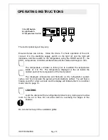
Страница 18: ...mperature controller is factory set to maintain the temperature inside at 3 to 5oC The temperature displayed is the air inside the cabinet and not the temperature of the food product The displayed temperature will fluctuate as the refrigeration system cycles At 2 hour intervals the system will automatically defrost You will hear a hissing sound for a few seconds and the display will indicate that ...

Страница 19: ...he operator side of the appliance Access the condenser by removing the screw holding the grille in place using the Allen key provided Use a vacuum cleaner to suck any debris from the face of the condenser and replace the grille For drop in models the condenser is located at the front of the drop in module and can be brushed down using a stiff bristled brush REPLACING THE LIGHT Disconnect the unit ...

Страница 20: ... in addition to and does not diminish your statutory or legal rights The guarantee does not cover Accidental damage misuse or use not in accordance with the manufacturer s instructions Consumable items Damage due to incorrect installation modification unauthorised service work or damage due to scale food debris build up etc The manufacturer disclaims any liability for incidental or consequential d...

Отзывы: